I finally got around to assembling one of the pcb’s I had printed up for this project, and it works!
The circuit is just an STP16 chip sinking current on 16 common cathode RBG LEDs, and three transistors selecting whether red, green, or blue is active. The 16 buttons are tied to the STP16 pins as well, and all the other sides of the buttons are tied together and run out to the header. An AVR ATtiny84 connects over the header. The AVR “brain-board” is nothing more than the AVR chip itself, plus a button I use to change modes, and an 6-pin ISP header and resistor used for re-programming the chip. Seeing as the parts count could be exactly one 14-pin chip, future version of the board should probably have the option of putting that chip on the board directly.
This approach is unique because it uses one STP16 chip to sink the LED current (like the Peggy 2) and also uses that same chip to produce the scanning that reads the buttons. Thus only 7 pins are needed on a single microcontroller to control a very long string of boards: 3 pins for the three colors, 1 pin for reading the buttons, and 3 pins for shifting bits into the STP16. This is much simpler and equally powerful approach as Sparkfun’s SPI boards, which uses an 18-pin current sink chip, and two 16-pin shift register chips, as well as 13 pins on the IC. I have yet to test how many boards can be controlled by a single microcontroller, so we’ve yet to see how my approach really measures up…
Full color (24-bit, which is 8-bit per “channel”) is possible, as seen in the video. However it’s fairly processor intensive and there’s not many free clock cycles. I’m using a software PWM, so using hardware PWM would speed things up of course.
- Schematic (jpg)
- Schematic (gEDA gschem file)
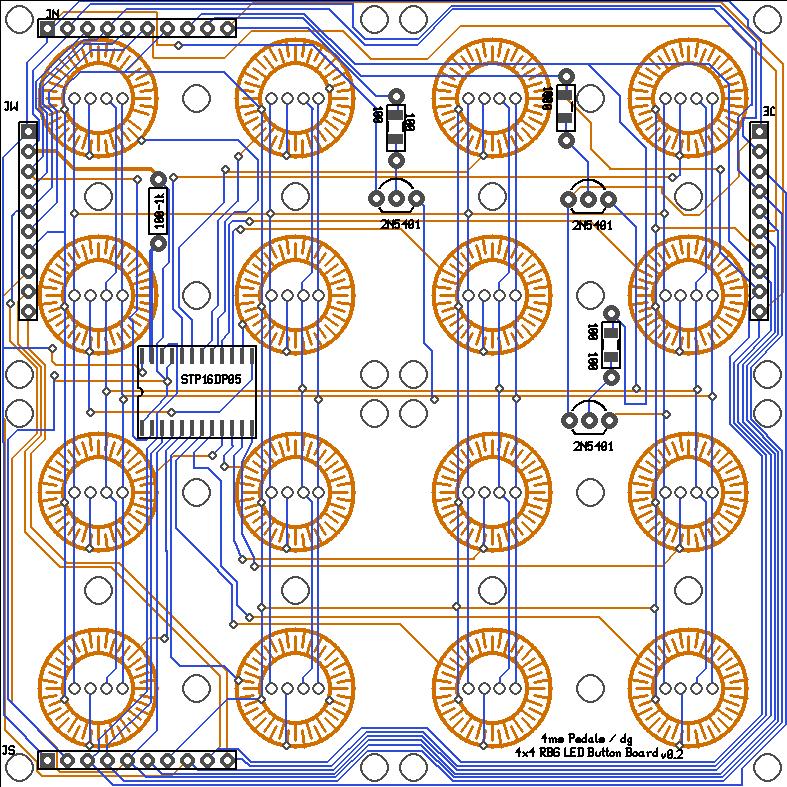
- PCB image (jpg)
- Totally un-optimized, randomly commented, proof-of-concept source code (avrstudio4 project in avr-gcc): bx3d_tiny84.zip