
In 2010, Ezra Masch, who was pursuing his MFA at University of Texas, Austin at the time, approached me about designing the electronics for a color organ project he was planning to show at UT and at the Artpost during the East Austin Studio Tour. We went over some ideas and ended up building a 72-channel light display controlled by a Rhodes piano. Each key on the Rhodes would not only play a note (like a normal Rhodes), but would also trigger an AC circuit to turn a light on. The lights were arranged by color so that the same notes were the same colors in any octave (F=red, G=orange, A=yellow, etc). This blog post is intended to document my work on the project, which was mainly the electronics.
Overview
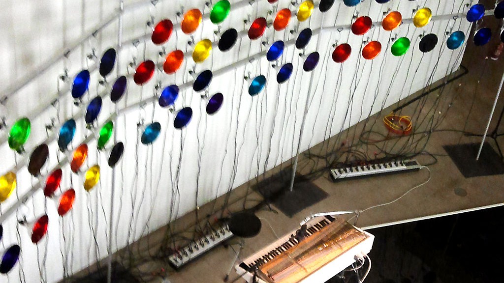
Our system consisted of mounting a strip of tact buttons under the keys of the Rhodes, and running those signals to three DB-25 ports (aka parallel port cable, or old-school printer cable) on the back of the Rhodes. The DB-25 cables ran to three AC boxes, each box having 24 normal household 120V electrical plus on it. Each of these outlets corresponded to a key on the Rhodes. Each of the 72 clip-lamps plugged into one of the electrical plugs and was mounted on a rack frame the Ezra designed and built.

Button board
I designed a PCB that we could mount 16 buttons onto, so we needed 6 of these to get 72 buttons. (They’re the same buttons I used on the Autonomous Bassline Generator). We both assembled and soldered the PC-boards, they’re a good quality so it went fast. The PCBs themselves mounted to an aluminum angle, which provided enough rigidity to keep a constant level under the keys. Ezra designed and fabricated this angle with a slotted mounting system so we could precisely set the clearance between the button-board rail and the keys. This was critical for ensuring good play-ability.
Each button closed a circuit to feed a DC voltage to one of the header pins. Since there’s no power normally on a Rhodes (they work wonderfully like guitar pickups), the DC voltage was provided by a power-supply in the AC boxes.

Inside the Rhodes
Traces ran from the buttons to 2×8 header pins on the end each PCB. Six ribbon cables (16-conductors each) ran from the header pins to a breakout board in the back that had three DB-25 plugs. With one pin reserved for a reference voltage, and ground taken from the shield, each DB-25 left us with 24 signal pins, meaning 24 lights could be switched on/off from one DB-25 cable.
The whole system could be removed from the Rhodes without any damage or change to this vintage instrument (besides the DB-25 jacks mounted the rear).

AC boxes
The other end of each DB-25 cable went to an AC box. When a key was pressed on the Rhodes, the DC voltage coming from the button boards would trigger an SCR to allow AC current to flow to one of the AC outlets. In the foreground you can see there’s two identical yellow PCBs, each with 12 SCRs on it. The IC sockets are there to hold resistor arrays (which helped to keep stray currents from falsely triggering the circuits). It took us a few hours to do the wiring together. Afterwards, the wires were zip-tied and organized neatly before the boxes were closed (not shown in photos). Ezra built the boxes out of wood and aluminum angle, and mounted all the AC outlets before we began the wiring process.
Also you can see the DC power supply (green PCB, foreground), which was just a wall-wart I busted open and mounted inside each AC box. The DC voltage goes through the DB-25 cable to the button boards inside the Rhodes. This setup is not ideal from a signal/noise perspective because the reference voltage is running inside the same shielded cable (the DB-25) as the signal conductors. However we stuck with this method instead of generating the DC voltage inside the Rhodes because it meant the expensive Rhodes would be modified as little as possible, and it also kept any AC power out of the Rhodes itself (which could contaminate the audio). We also wanted to avoid using batteries since this would be set up for long periods of time in a musuem/gallery setting. So the DC came off the same AC circuit that’s switching the lights, and ran along side the switching voltages, and with some extra attention to keeping noise out of the system, it worked great.


Setup
For setup, Ezra mounted all the lights in a pattern on a rack (approximately 30′ x 10′). A group of us spent a long night extending the cords of all 72 lights so they would hang down to the AC boxes with some comfortable slack. The Rhodes was in the center of the light racks, behind the performer’s back, with it’s three printer cables running out to the AC boxes. The audience stood or sat in front and watched the wall of light flash behind and above the performer.

Testing
But before the audience showed up, we tested and tweaked. The button board had to be adjusted very precisely in order to maintain a consistent triggering force across the whole keyboard. Also we found some cheaper DB-25 cables caused false-triggering, so we had to use good ones (which are hard to find, since they have fallen out of demand with the advent of USB). A few trips to the computer Goodwill and Radioshack solved this.

“Music of the Spheres” from The Daily Texan
Performances
Ezra gave his master’s show at UT, in the sculpture building. Later that week he performed at the Artpost as a part of the East Austin Studio Tours, with smoke machines, clapping and cheering, and I even recall a limo pulling into the space.
A few months later (?) it was again set up at the Visual Arts Center at UT. This time there were more performers, elaborate costumes, and psychedelic patterns on the walls.


Critique
At the end of the day, we were pretty happy: the experiment was a success. Along the way we had to sacrifice a few ideals to meet deadlines and make the project practical. One big one was the sustain pedal. Since the buttons responded only when a key was physically held down, the lights would turn off when the key was released even if the sound continued because the sustain pedal was held down. This meant the lights didn’t quite “ring” the same way the sound would. However, watching the lights flicker and flash in time, space, and color to the music was mesmerizing enough. Some ideas to add this sustain functionality would be using a 72-channel CMOS latch circuit (use the sustain pedal to latch the data from the buttons, and then clear it when the pedal is released). Or a micro-controller circuit could accomplish this easily (as well as fancy stuff like arpeggiation!)
A critique of the electrical circuit would be that the unit is not grounded well. The DC ground needs to be connected to the AC neutral in order for the SCRs to trigger. No exposed metal is connected to the neutral, so there is little risk of shock, but I didn’t like having to use AC neutral as the interference shield in the long DB-25 cables. If a performance space had bad ground in the building, or if there was noisy AC power, it might effect how well the SCRs trigger, and that could cause problems. We addressed this issue in our next project, by using relays instead. More on that in another post…
Another issue was the use of physical buttons. A slight force was necessary to close the button, so the Rhodes didn’t respond the same way it did without the button board installed. With a little practice, it could be ignored, but it would have been nice to use something optical or magnetic/Hall effect. But, getting 72 optical or magnetic switches to operate without interference in tight quarters seemed daunting, so we chose the mechanical switch approach despite the change in “feel” on the instrument.
Finally, the system looked much better when played in the dark. This might be obvious, but it had an impact since the first performance had to be done in the daytime. Ezra and I considered this when we collaborated on our next project….the Light Matrix… To be continued
