Drum-Triggered Room of Lights (Crane Arts/Ice Box Installation #3)

synth-view-of-room
Ice Box gallery in the Crane Arts Building, Philadelphia. We installed 183 fluorescent light tubes in the 50′ x 100′ x 20′ room, and controlled them via a drum set and analog modular synth. No computers were involved!


A Matrix of 183 Fluorescent Light Tubes Controlled by a Live Drummer

Read about the first two installations on this blog:
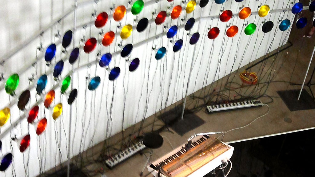
First installation: March 2012 at the University of Texas in Austin
Second installation: June 2014 at Forcefield Project in Philadelphia
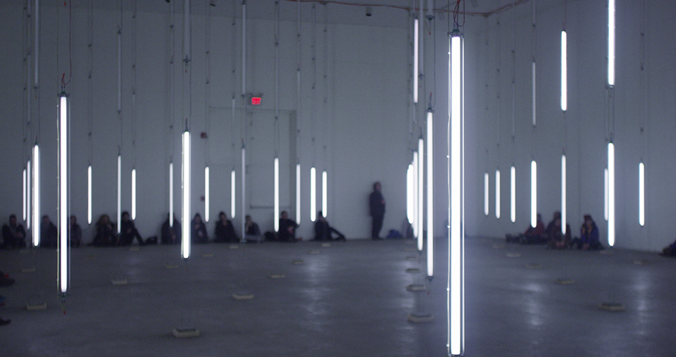
Third installation: December 2014 at Crane Arts Center, Ice Box room in Philadelphia

In December 2014, Ezra raised funds through a kickstarter to pay for a 3rd installation of the Light Room (aka Big Bang Project aka Drum Triggered Room of Lights). This time it would be bigger than every (twice as many lights) and be open to the public in a well-know art gallery. Ezra, Rinda, and a bunch of volunteers did the wiring, and I flew out to Philly a week before the show to set up the low-voltage circuitry, calibrate the system, and troubleshoot problems.

people assembling
People gathering in the Ice Box before the show.

System overview

Simplified flow diagram of how the drums control the lights

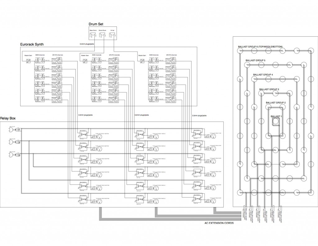
Take a look at the diagram above, it shows the basic components that we used to control the lights with the drums.

In a nut-shell:
Each drum gets a microphone. Each mic is split into six channels. Each channel controls a relay. Each relay controls a group of lights. There’s 3 drums, 18 channels, 183 lights.

In a slightly larger nut-shell:
When a drum is struck, the contact microphone sends a signal to the synth. This is amplified by the pre-amp and then split into six channels. Each channel has a Level Set (a volume knob), which determines how much signal needs to be present on the mic before triggering the next stage, the Pulse Generator. The Pulse Generator cleans up the analog mic signal with a comparator, and then outputs one clean pulse every time the threshold is crossed. The more that each channel’s level is turned down with the Level Set, the harder the drum has to be hit to make the Pulse Generator fire. Thus we’ve created six amplitude bands.  Finally, the Pulse Generator’s output is sent to an AC relay, which turns on a 120VAC circuit that powers one or more ballasts. Each ballast powers up to four lights.

Pulse Width
A cool thing about the one-shot inside the Pulse Generator is that we can control the pulse width. The pulse width determines how long each group of lights will stay on once it’s triggered. This means if we hit the drum at maximum strength, all the lights will go on at about the same time, but they can turn off at different times based on each of their pulse width settings. We used this technique to create animation effects such as making the lights seem to collapse into the center of the room.

The verbose explanation:
Below is a diagram of the entire circuit, from drum set to lights. We’ll break it down section by section:

light-room-overview


Drum Set

ice_dtl_7webWe had a simple drum kit: kick, snare, hi-hat. Each of the three drums had a contact mic taped to their resonating surface. The mics then ran to the next section, the synth…
section-drum


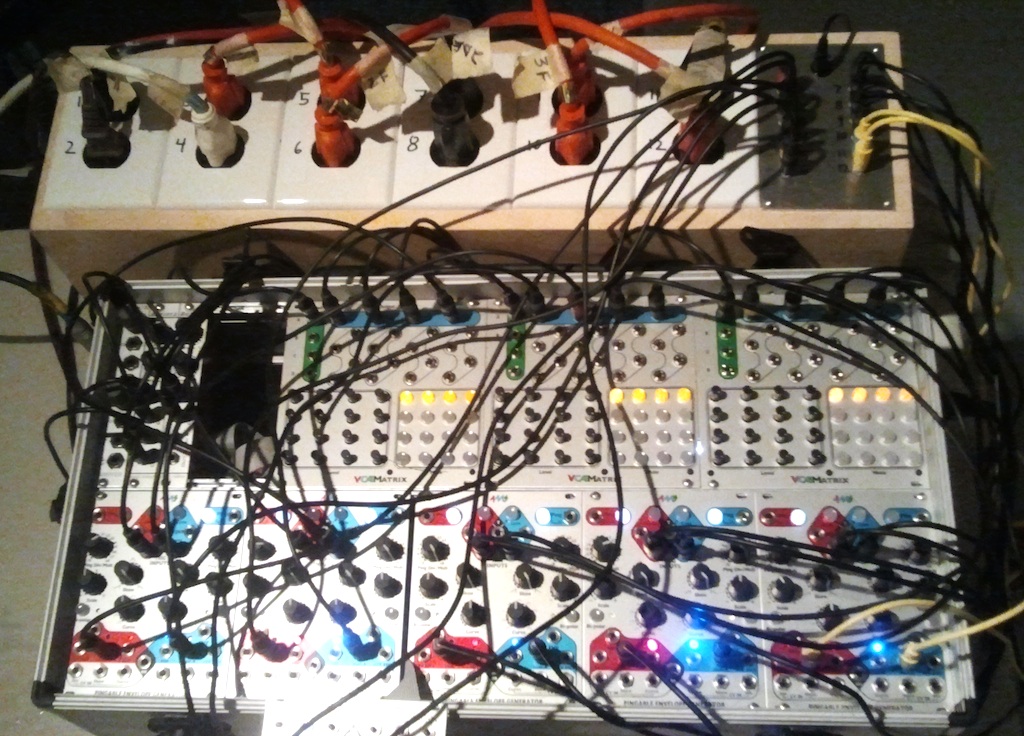
Low-voltage processing: The Synth

The patch
The synth converted the drum mic signals into pulses that drove the relays
section-synth
The Eurorack synthesizer takes the 3 drum signals and converts them to 18 pulse outputs.

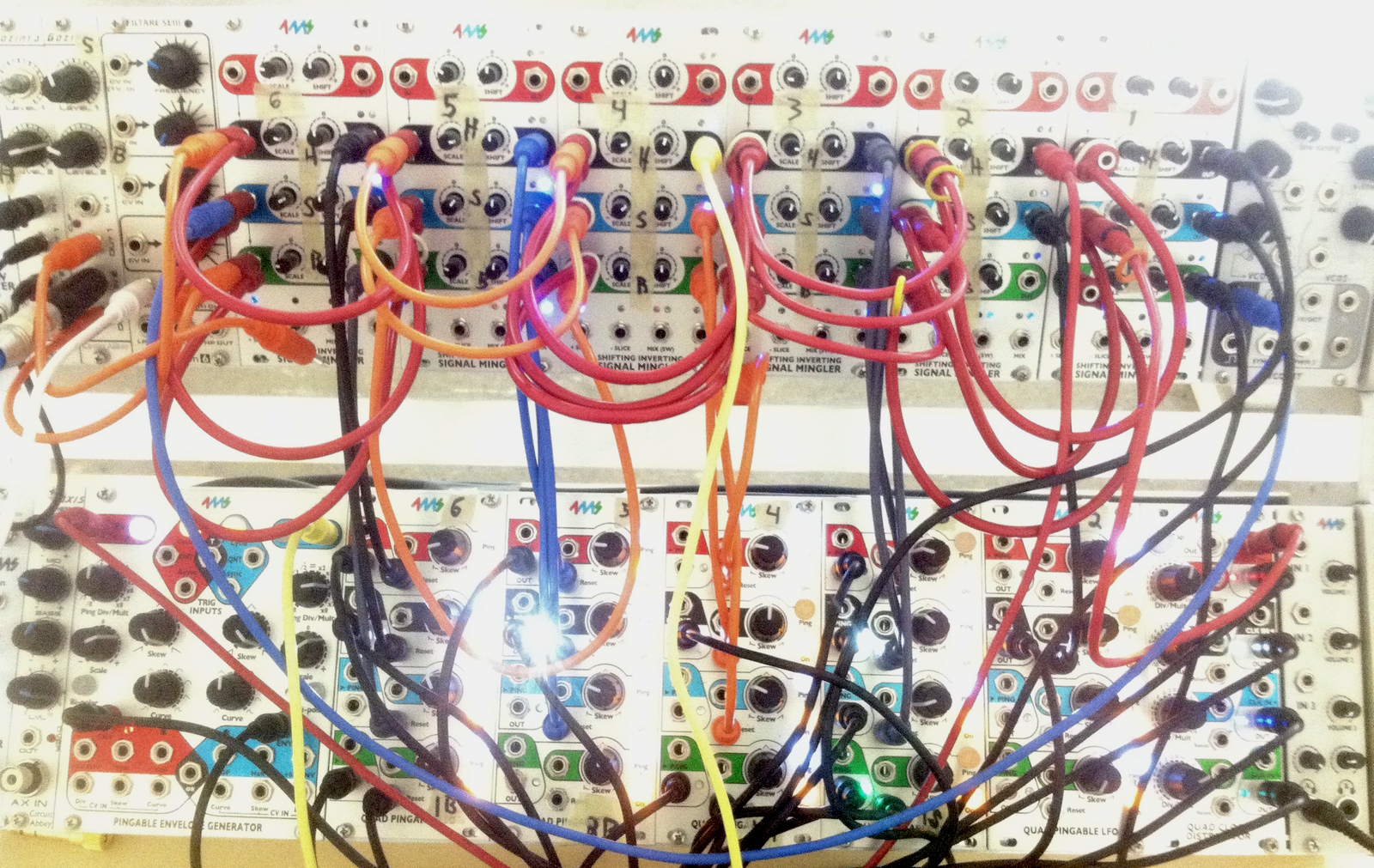
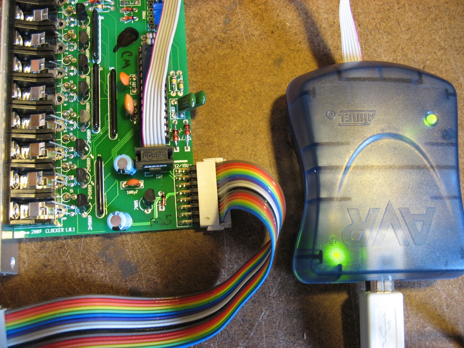
The synth was built from off-the-shelf eurorack modules: 4ms QPLFO, 4ms SISM, Circuit Abbey Gozinta, and Division 6 Filtaire. I loaded some custom firmware onto the QPLFO to make it only output pulses and always operate in one-shot mode. Since I work at 4ms Company, I have access to lots of 4ms modules, so I used them as much as possible!

The Master Gain (preamp) modules were Gozintas. I used six SISMs for the Attenuate/Offset function, leaving the red (top) channel of each module open. Then I used five QPLFOs for the Pilse Generators (comparator/one-shots). The QPLFOs had firmware running that caused them to generate a pulse wave when receiving a trigger on the Reset jack. This is the same as the QPLFO’s normal “one-shot” mode, except it outputs a square wave instead of a triangle/saw/ramp. Also, giving it a clock won’t pull it out of one-shot mode. I could adjust the pulse width via the Skew knob and by tapping a tempo on the Ping button. I could also mute a channel with the Mute button.

The outputs of the QPLFO channels went to the Relay Box, via 1/8″ cables.


High-voltage: Relays

relaybox-front

section-relay
Relay box schematic

interface

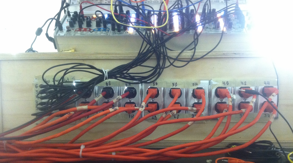
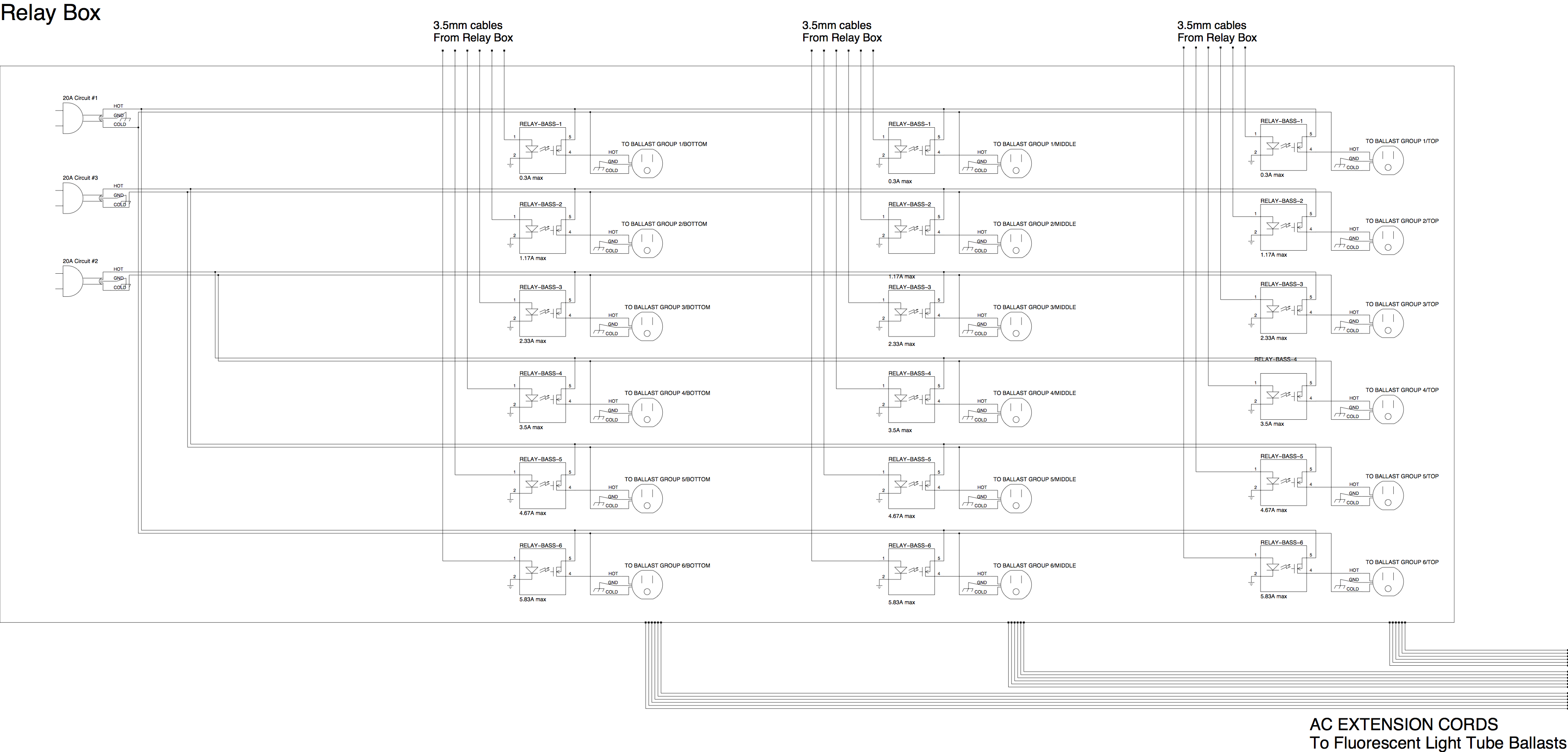
The Relay Box has 18 low-voltage inputs (3.5mm jacks) and 18 high-voltage outputs (120VAC outlets). It also has three standard AC wall plugs (20A) that provide power to the outlets when the corresponding relay is turned on by the low voltage inputs.

One relay with large 10A heatsink

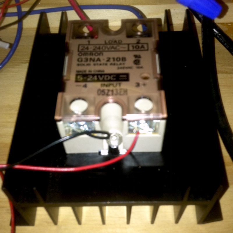
Inside the box are 18 relays, the G3NA-210B by Omron. These are solid-state relays, which is crucial because we’re switching at audio rates. Ordinary electro-mechanical relays fail at these rates (we learned this the hard way on our first installation!). Another critical parameter of the relay is the 5V-24VDC input. Since the synth outputs 5V DC, we can directly trigger the relays from the synth and don’t need any level conversion. These relays can handle up to 10A if heatsinked properly, and 4A with no heatsink.

inside relay boxThe wiring was straightforward: each 3.5mm jack was wired directly to the input on a relay. One terminal on the output side of each relay was wired to an outlet, and the other terminal was wired to the hot line of the incoming AC. The cold line of the incoming AC was wired directly to the other side of the outlet.

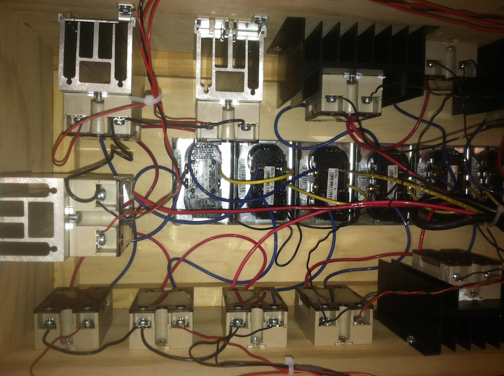
Six of the relays controlled four or more ballasts, and each ballast required about 1.17A  (4 x 32W bulbs x 1.1 efficiency rating = 120VAC x 1.17A). Thus, these six relays needed to be heatsinked because they would be loaded with over 4A (4 x 1.17A > 4A). We used large heatsinks which allowed for up to 10A (more than enough). Another three heatsinks powered three ballasts each (12 bulbs) which is close to the maximum of 4A. Rather than push the limit, I decided to heatsink these three relays with smaller heatsinks. The final nine relays powered less than 12 bulbs each, so they had less than 4A passing through them at any given time, and therefore did not need a heatsink.

Coming out of the relay box were 18 extension cords, which we attached to the wall and ran along the ceiling to the ballasts.
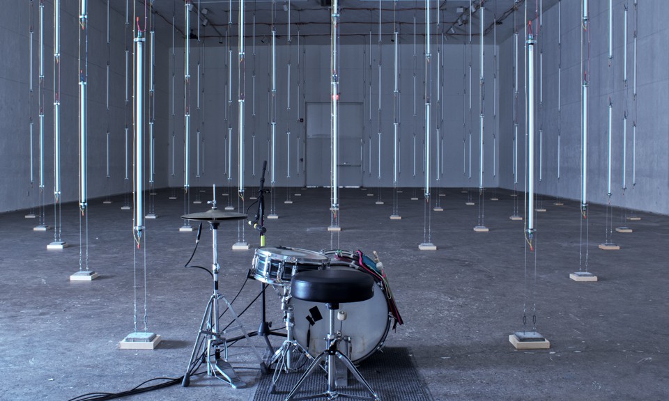

Display: The Lights

grid
Running all 183 light tubes at the same time to test for bad bulbs

ice_dtl_1webice_dtl_5webice_pan_01web


section-room
Overview of light tube placement, and groupings. Dimensions of the room and location of lights (circles) are to scale!

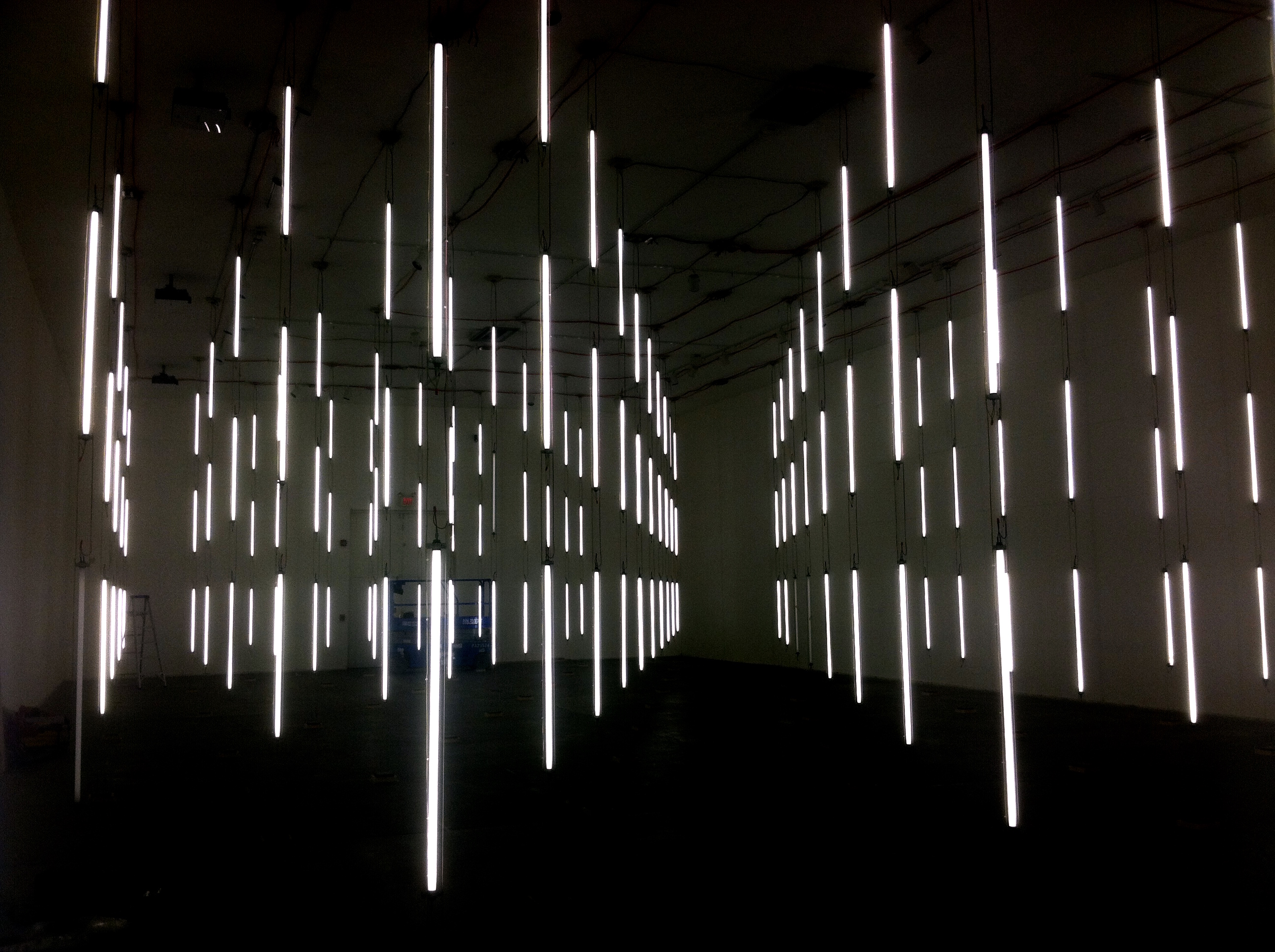
The lights were arranged in groups and layers. Look at the room layout drawing above. Each circle is a column of three lights (low, middle high). There are also six groups, each of which is a concentric rectangles, including the center light. The outer rectangle is called Group 6, the next is called Group 5, etc… and the center light is called Group 1. Each of the six groups exists on three layers (hi-hat, snare, or bass), so in total we have 18 groups.

The fluorescent tubes are powered by ballasts. Each ballasts powered four lights each, except the three Group 1 ballasts powered a single bulb each. For Group 6, which has 20 lights, we used five ballasts. The AC inlets of these five ballasts were tied together and one long extension cord ran back to the relay box. Each of the 18 groups was wired like that, so we had 18 extension cords running along the ceiling. In total there were 45 quad-bulb ballasts and 3 single-bulb ballasts.

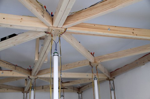
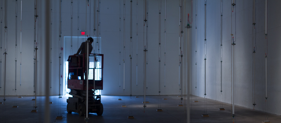
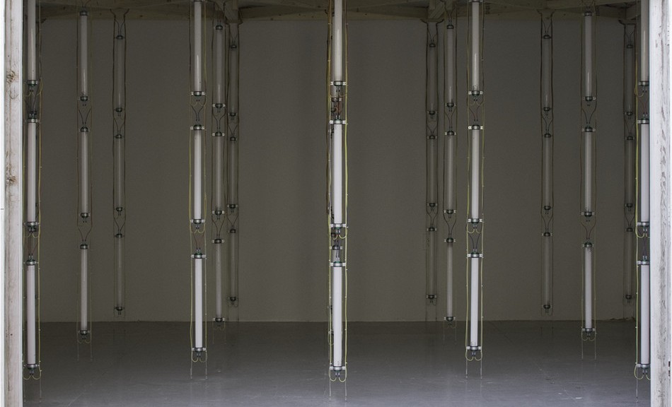
Floating columns of light
The columns of lights were not touching the floor. Two steel cables were tied to the ceiling and ran vertically down to attach to a concrete paving stone. Each of the 61 columns was essentially a plumb bob. A block of wood glued to the floor prevented them from swinging around, but the plumb-bob feature meant that each one was perfectly vertical. The light tubes were secured to the steel cables using brackets that Ezra and the volunteers hammered out from flat brackets. The wires that ran power to the lights dropped down parallel to the steel cables.  At the top of each column was a wooden plate with terminal blocks to attach the wires. This made installation a lot easier because some of the work could be done on the ground.
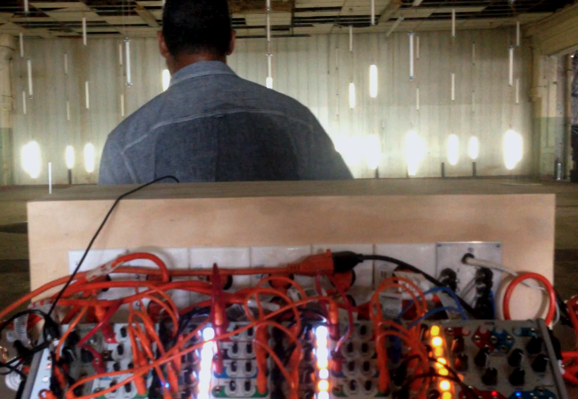
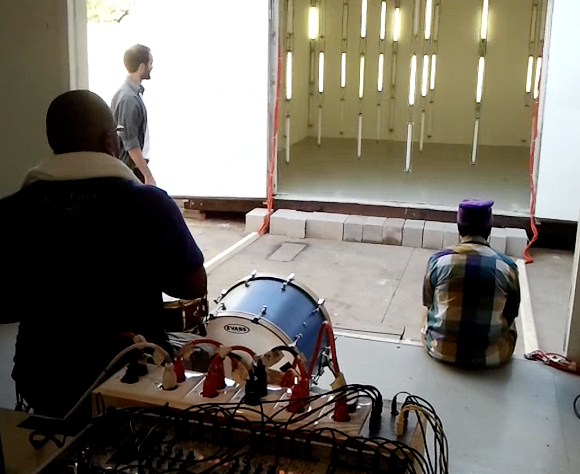
The Performance

Ice_still_14_web2Ice_still_15_web4

We had a preview performance for the volunteers and kickstarter funders, and then we had two performances that were free and open to the public. We also ran the show a few times for the professional videographers (and I’ll post their footage when I get it!)

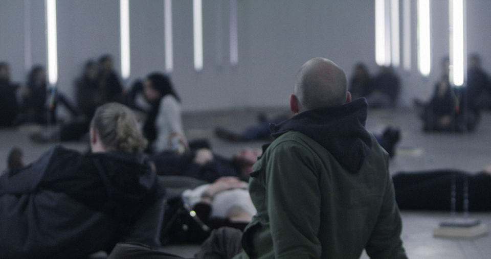
The shows went great, they were well-attended and there were very few technical issues. The audience seemed transfixed by the flashing lights and reverberating rhythms. Some people layed on the floor and stared up, and others sat against the wall in order to see as much as possible.

What we learned

  • The wiring between instant-start fluorescent ballasts and the bulbs is subject to capacitive loading and should be as short as possible (<16′) or else the bulbs might be erratically dim and/or flickering. Luckily this added some “texture” to the otherwise all-white room and all-white lights, but it was an annoying technical detail that we weren’t prepared to overcome because we only realized it after all the wiring had been done.
  • LEDs might be worth trying out next time, since fluorescents can only be flicked on/off so many times before they fail.
  • It’s very hard for a drummer to play six distinct dynamics on each drum (pp, p, mp, mf, f, ff). It’s even harder to jumper between arbitrary dynamic levels on multiple drums at the same time while keeping a rhythm going. More than 2 days of practice would be necessary for even a very advanced drummer.
  • It’s very hard electronically to separate an analog mic signal into six different bands of peak amplitude. Using a low-pass filter on the hi-hat helped a lot (as well as peaking it out before the filter, which made it sound like a tom-tom drum after the LPF). Setting the knobs to pick out six distinct bands was very touchy. Next time we might try a true envelope follower, or perhaps a DSP engine.  We might also need to use something else besides a contact mic (perhaps a force-sensing resistor on the drum head?)
  • A bunch of people can come together and make something amazing happen!

Rhodes piano 72-channel color organ

Rhodes Piano Overhead view
Rhodes Piano Color Organ installation at University of Texas, Austin.

In 2010, Ezra Masch, who was pursuing his MFA at University of Texas, Austin at the time, approached me about designing the electronics for a color organ project he was planning to show at UT and at the Artpost during the East Austin Studio Tour. We went over some ideas and ended up building a 72-channel light display controlled by a Rhodes piano. Each key on the Rhodes would not only play a note (like a normal Rhodes), but would also trigger an AC circuit to turn a light on. The lights were arranged by color so that the same notes were the same colors in any octave (F=red, G=orange, A=yellow, etc). This blog post is intended to document my work on the project, which was mainly the electronics.

Overview

Our system consisted of mounting a strip of tact buttons under the keys of the Rhodes, and running those signals to three DB-25 ports (aka parallel port cable, or old-school printer cable) on the back of the Rhodes. The DB-25 cables ran to three AC boxes, each box having 24 normal household 120V electrical plus on it. Each of these outlets corresponded to a key on the Rhodes. Each of the 72 clip-lamps plugged into one of the electrical plugs and was mounted on a rack frame the Ezra designed and built.

Schematic for the 3 PCBs. A 72-key Rhodes requires 3 PCBs. The fourth section shows the wiring for the AC boxes

Button board

I designed a PCB that we could mount 16 buttons onto, so we needed 6 of these to get 72 buttons. (They’re the same buttons I used on the Autonomous Bassline Generator). We both assembled and soldered the PC-boards, they’re a good quality so it went fast. The PCBs themselves mounted to an aluminum angle, which provided enough rigidity to keep a constant level under the keys. Ezra designed and fabricated this angle with a slotted mounting system so we could precisely set the clearance between the button-board rail and the keys. This was critical for ensuring good play-ability.
Each button closed a circuit to feed a DC voltage to one of the header pins. Since there’s no power normally on a Rhodes (they work wonderfully like guitar pickups), the DC voltage was provided by a power-supply in the AC boxes.

Button board
Button board, mounted to custom rail.

Inside the Rhodes

Traces ran from the buttons to 2×8 header pins on the end each PCB. Six ribbon cables (16-conductors each) ran from the header pins to a breakout board in the back that had three DB-25 plugs. With one pin reserved for a reference voltage, and ground taken from the shield, each DB-25 left us with 24 signal pins, meaning 24 lights could be switched on/off from one DB-25 cable.

The whole system could be removed from the Rhodes without any damage or change to this vintage instrument (besides the DB-25 jacks mounted the rear).

Inside the Rhodes
Inside the Rhodes, the button board wired with ribbon cables leading to the DB25 ports on the back (not shown)

AC boxes

The other end of each DB-25 cable went to an AC box. When a key was pressed on the Rhodes, the DC voltage coming from the button boards would trigger an SCR to allow AC current to flow to one of the AC outlets. In the foreground you can see there’s two identical yellow PCBs, each with 12 SCRs on it. The IC sockets are there to hold resistor arrays (which helped to keep stray currents from falsely triggering the circuits). It took us a few hours to do the wiring together. Afterwards, the wires were zip-tied and organized neatly before the boxes were closed (not shown in photos). Ezra built the boxes out of wood and aluminum angle, and mounted all the AC outlets before we began the wiring process.

Also you can see the DC power supply (green PCB, foreground), which was just a wall-wart I busted open and mounted inside each AC box. The DC voltage goes through the DB-25 cable to the button boards inside the Rhodes. This setup is not ideal from a signal/noise perspective because the reference voltage is running inside the same shielded cable (the DB-25) as the signal conductors. However we stuck with this method instead of generating the DC voltage inside the Rhodes because it meant the expensive Rhodes would be modified as little as possible, and it also kept any AC power out of the Rhodes itself (which could contaminate the audio). We also wanted to avoid using batteries since this would be set up for long periods of time in a musuem/gallery setting. So the DC came off the same AC circuit that’s switching the lights, and ran along side the switching voltages, and with some extra attention to keeping noise out of the system, it worked great.

Inside the power switching box, pre-wiring
Inside the power switching box, before wiring the AC outlets. The SCR boards (left and right) are visible, as well as the DC power supply (bottom, green)
Inside power switching box, post-wiring
Inside the power-switching box, after wiring the AC outlets

Setup

For setup, Ezra mounted all the lights in a pattern on a rack (approximately 30′ x 10′). A group of us spent a long night extending the cords of all 72 lights so they would hang down to the AC boxes with some comfortable slack. The Rhodes was in the center of the light racks, behind the performer’s back, with it’s three printer cables running out to the AC boxes. The audience stood or sat in front and watched the wall of light flash behind and above the performer.

Power switching box, in use
Power switching box (1 of 3), connected to 24 lamps

Testing

But before the audience showed up, we tested and tweaked. The button board had to be adjusted very precisely in order to maintain a consistent triggering force across the whole keyboard. Also we found some cheaper DB-25 cables caused false-triggering, so we had to use good ones (which are hard to find, since they have fallen out of demand with the advent of USB). A few trips to the computer Goodwill and Radioshack solved this.

Ezra testing the unit
Ezra Masch, testing the channels before a performance

“Music of the Spheres” from The Daily Texan

Performances

Ezra gave his master’s show at UT, in the sculpture building. Later that week he performed at the Artpost as a part of the East Austin Studio Tours, with smoke machines, clapping and cheering, and I even recall a limo pulling into the space.

A few months later (?) it was again set up at the Visual Arts Center at UT. This time there were more performers, elaborate costumes, and psychedelic patterns on the walls.

In costume
In costume, performing. In the foreground are silver-painted greco drummers

Critique

At the end of the day, we were pretty happy: the experiment was a success. Along the way we had to sacrifice a few ideals to meet deadlines and make the project practical. One big one was the sustain pedal. Since the buttons responded only when a key was physically held down, the lights would turn off when the key was released even if the sound continued because the sustain pedal was held down. This meant the lights didn’t quite “ring” the same way the sound would. However, watching the lights flicker and flash in time, space, and color to the music was mesmerizing enough. Some ideas to add this sustain functionality would be using a 72-channel CMOS latch circuit (use the sustain pedal to latch the data from the buttons, and then clear it when the pedal is released). Or a micro-controller circuit could accomplish this easily (as well as fancy stuff like arpeggiation!)

A critique of the electrical circuit would be that the unit is not grounded well. The DC ground needs to be connected to the AC neutral in order for the SCRs to trigger. No exposed metal is connected to the neutral, so there is little risk of shock, but I didn’t like having to use AC neutral as the interference shield in the long DB-25 cables. If a performance space had bad ground in the building, or if there was noisy AC power, it might effect how well the SCRs trigger, and that could cause problems. We addressed this issue in our next project, by using relays instead. More on that in another post…

Another issue was the use of physical buttons. A slight force was necessary to close the button, so the Rhodes didn’t respond the same way it did without the button board installed. With a little practice, it could be ignored, but it would have been nice to use something optical or magnetic/Hall effect. But, getting 72 optical or magnetic switches to operate without interference in tight quarters seemed daunting, so we chose the mechanical switch approach despite the change in “feel” on the instrument.

Finally, the system looked much better when played in the dark. This might be obvious, but it had an impact since the first performance had to be done in the daytime. Ezra and I considered this when we collaborated on our next project….the Light Matrix… To be continued

PCB Crosstalk: Capacitance of Parallel Traces

A big problem in dense PCB layout is crosstalk between traces.

Purely analog and mixed analog/digital boards are more prone to this, especially when the audio path is expected to be clean and free of noise. In a pure analog board, you might see a signal from one channel on a different channel, faintly in the background, or you might not be able to turn a signal all the way down/off like the circuit was designed to do. In a mixed signal board, you might hear a periodic ticking sound when a microcontroller updates an LED or reads from an external memory chip, or you might see an ADC value change on one channel when you turn the knob of another channel.

There could be many causes for these problems, but in this article I’d like to discuss one such cause: parallel traces. Other problems (each of which deserves an article to itself) could be poorly designed ground/return paths, inadequate power regulation, use of chips with poor PSRR (combined with inadequate regulation), etc.

Parallel traces on the board act like capacitors and signals you routed along one trace can “mysteriously” appear in another trace. Since capacitors conduct higher frequencies more easily than lower frequencies, a indicator that you might be dealing with trace-to-trace crosstalk is if higher frequencies are bleeding more readily than lower frequencies. This doesn’t prove that the path of the bleed is trace-to-trace capacitance, but it’s worth investigating!

For example, let’s say we have a simple four channel analog mixer. Let’s say we’re testing our first prototype and we find that a 10kHz sine wave fed into channel 1 can be heard on the main output even when channel 1’s level pot is turned down to 0. However, a 500Hz sine wave of the same amplitude isn’t heard at all. Further investigation shows that the 10kHz bleed can be controlled by channel 2’s level pot. Aha! We now should take a look at our board layout and look for traces that carry channel 1’s signal (before the level pot attenuates it) that are near traces carrying channel 2’s signal (also before the level pot attenuates it).

Let’s say we found two traces that might be causing the bleed. How do we find out for sure if this is the cause of the problem?

Do the math!

The formula for Capacitance between two traces is:

C = e0 * eR * t * (L/d)

Where:
e0 is a constant (the permittivity in a vacuum), and eR is another constant determined by the PCB material
t is the thickness of the trace
L is the length of the parallel section
d is the separation between the traces

In a typical board, the material is FR4 and the traces are 0.003mm (0.12mil).
e0 = 8.84 pF/m
eR = 4.7 (roughly)
t = 0.003mm = 0.12mil

Since all these are constant, we can multiply them together and simplify our equation like this:

e0 * eR * t = 0.000125pF

C = 0.000125pF * (L/d)

Back to our example, if our traces were 6mil apart, and parallel to each other for a distance of 600mil:

C = 0.000125pF * 600mil/6mil = 0.0125pF

So it’s essentially like we soldered a 0.01pF capacitor between those two traces.

How much bleed could that cause?

I = C * dV/dt
where dV/dt is the rate of change of the voltage, which is essentially amplitude * 2 * frequency of an analog sine wave, or rise time of a square wave

So for a 10kHz sine wave of 10V amplitude, we have a dV = 10V and dt = 1/(10kHz * 2) . We multiply the frequency by 2 because in a sine wave the voltage changes by 10V twice for every period (once rising and once falling).
dV/dt = 10V / (1/20kHz) = 10V/50us = 1V/5us = 0.2V/us

So the induced current would be
I = C * 0.2V/us = 0.01pF * 0.2V/us = 0.002V pF/us = 2nA

Hmm, 2nA doesn’t sound like much, does it? Well… let’s say the receiving trace is an input to a JFET opamp. The impedance could be around 100Mohms,. The induced voltage will be:

V = I * R
V = 2nA * 100Mohms = 200mV = 0.2V

And that’s quite audible!

Much thanks to: https://www.edn.com/electronics-blogs/bakers-best/4426162/PCB-signal-coupling-can-be-a-problem

Drum-Triggered Room of Lights (Forcefield installation #2)

Installation a the Force Field Project
Installation at the Force Field Project

 Doing it a second time…

The first installation was in Austin, TX, in a trailer behind the Sculpture Department at the University of Texas. In the spring of 2014, Ezra contacted me about doing the show in Philadelphia, but doing it bigger and better and re-building everything from scratch. Sure, why not?

This time we wanted to make some improvements. We used more columns of lights and spaced them out so that the audience could walk bewteen the columns of lights. We also agreed to use solid-state relays instead of magnetic relays, because so many of the magnetic ones had stuck open or closed after being hit with high frequencies for so long. Ezra also had some better ideas for quick starting ballasts and tubes, and I had some better ideas for the synth patch.

The installation was set up for Force Field Project in a warehouse in the Kensington neighborhood of Philadelphia, PA, in June 2014. I flew in a few days ahead of time, assembled a new relay box and helped with wire the 75 light tubes to ballasts, and the ballasts to the relay box. Other artists were milling about, assembling their projects all over the building (including inside the ventilation shafts and on the roof). Sadly, the party was closed to the public at the last minute because of zoning/code issues. We were able to run the installation anyways and take videos, but only the artists got to see it in person. It was awesome– it was amazing to witness the room explode in light to the drums, and walk around in the matrix. We were determined to let the public see it too, so six months later we set it up in a (legit) art gallery, making it bigger and better than ever.

Drum Installation, pt. 2


Drum Installation, pt. 1

Setting up
Setting up

The mics and the synth

Just like last time, there were three drums, each with a contact mic. Each contact mic ran into a pre-amp module that boosted the level (and gave me a master volume knob). Each pre-amp output ran into a Shifting Inverting Signal Mingler (SISM) module, splitting the signal into four outputs and giving me an attenuator on each output. This is how I set four different amplitude bands for each drum. The four attentuated outputs then went to the four channels of a QPLFO module running custom firmware to generate one-shot pulses. When the drummer hit hard, all four SISM channels would send a voltage greater than the QPLFO’s threshold and so all four QPLFO channels would send a pulse. When the drummer hit soft, one or maybe two QPLFO channels would send a pulse. I could control the pulse width of each QPLFO channel by tapping a tempo and/or adjusting the Skew knob. By adjusting pulse width and sensitivity of each light group, we could create some cool effects.

The relay box

The  QPLFO one-shot outputs ran into the relay box, turning on and off the solid-state relays. The relays took a DC signal and turned an AC circuit on and off. Each group of ballasts were plugged into a relay, and in turn the ballasts powered the fluorescent light tubes. Most of the ballasts were quad ballasts, so they powered 4 light tubes. The three center ballasts were single ballasts and they powered a single tube each. Each quad ballast needed 1.6A, and the single ballasts needed 0.4A each.

We had 12 relays and 21 ballasts, powering 75 lights. Three relays had large heatsinks that let them handle up to 10 amps in order to switch on/off three quad ballasts each (12 light tubes per relay) (note: we only needed about 6A per relay to power 12 lights, but having a better heatsink cost the same amount). Three relays had smaller heatsinks to let them switch on/off two quad ballasts each (8 light tubes). The remaining six relays didn’t need a heatsink because they only powered one ballast each (three quads and three singles).

The lights

The lights were arranged in a concentric grid (12 around 8 around 4 around 1 in the center). The grid was repeated three times in vertical layers. The larger circuits powered the outer rings of lights, and the smaller circuits powered the inner rings. The three layers corresponded to the three drums (kick = bottom layer, snare = middle layer, hi-hat=top layer). The concentric rings corresponded to the loudness of the drum. Remember how I mentioned I could dial in four different sensitivities per contact mic? Well that translates to four different loudness bands, meaning between one and four rings of lights would turn on whenever the drum was hit, depending on how hard it was hit.

Installation at the Force Field Project in Philadelphia, July 2014

We only got to play with this set up for an afternoon before we had to take it down. After spending a week installing everything into the building’s ceiling and floors, it was quite a rush to see it work.

Next: The third installation at the Crane Arts Center’s Ice Box: December 2014.

LED Buttons

I often get asked “Where do you get those buttons you use in your modules/kits?” or “Where can I get different colors of those buttons?”

If you just want a few buttons, a company called Well Buying makes a suitable replacement. Mouser carries them.

Here is the datasheet.

And here are some of Well Buying’s part numbers (search for these numbers at mouser.com if the links aren’t working):

PS004-L22NPR1AXTURXX (Red latching)

PS004-L22NPR1AXTUGXX (Green latching)

PS004-L22NPR1AXTUYXX (Yellow latching)

PS004-N22NPR1AXTURUG (Red/Green momentary)

PS004-N22NPR1AXBUBXX (Blue momentary)

PS004-N22NPR1AXRURXX (Red momentary)

PS004-N22NPR1AXTUYXX (Yellow momentary)

Mouser’s stock varies, and they may carry different colors, so try some searches on mouser to see if they have new stuff.

The caps on these buttons are translucent in a slightly different way than the ones we use in our kits and modules, but they are a drop-in replacement.

If you want to get a lot of buttons, I’ve heard that Well Buying will sell them to you direct at a much cheaper price. Or, if you prefer the exact buttons we use, then email me and I can refer you to our contact. Minimum order is several thousand pieces from our supplier.

Drum-Triggered Room of Lights (UT Austin installation #1)

A Matrix of 69 Fluorescent Light Tubes Controlled by a Live Drummer

aka “The Big Bang Project”

This is the second project I did with Ezra Masch (see the 72-channel Color Organ). We wanted to make a more immersive light environment that was more sensitive to the musician’s nuances than the Rhodes project.

Overview

This time we used a live drummer, with a kick (bass drum), snare, and hi-hat. We wanted each drum to control a bank of lights, with more lights turning on the harder the drum is hit. We decided to have 4 levels of “loudness”, or 4 amplitude bands  (soft, medium, loud, very loud).

We put the drummer in one room, and filled another room with the lights. There were three layers of 23 lights each, for a total of 69 fluorescent tubes arranged in a hexagonal matrix.


Drum and control room

Each drum had a sensor (piezo element, aka “contact mic”). The sensors ran into my modular synthesizer where the signals were split into 4 amplitude bands, cleaned up and sent to a custom-built relay box. The relay box had 12 relays, each one turning on a 120VAC circuit when it received a 5VDC signal on the input. Each relay controlled a bank of lights in another room.

The Patch

If you are familiar with modular synthesis, the following might make sense. Simply put: Contact mic -> Gain stage -> Four-way splitter -> Variable attenuation -> Trigger to gate converter (with Variable gate length) -> Relay box.
Here’s the patch in detail: I patched each of the three contact mics into a level booster (“Gozinta” module by Circuit Abbey), to provide lots of gain and to make use of the clipping LED (so I could check that the mic hadn’t fallen off!). I then patched each of these three outputs into a VCA Matrix channel configured as a single-input, four-output splitter. I attenuated each of these four outputs a little bit more than the previous one to provide four outputs, each of a different amplitude. These are the four amplitude bands for each mic. At this point we have 12 signals running (3 mics split into four bands each). Each of the twelve outputs ran to the Async Trigger jack on a Pingable Envelope Generator, to convert the audio wave into a steady gate signal. The P.E.G. has a triggering threshold of 3.5V, so by attenuating the signal on the VCA Matrix in different amounts I was effectively adjusting the amount of amplitude on the contact mic required to trigger each P.E.G. channel. I then took the gate output on the P.E.G. to trigger the relay box. By adjusting the Ping time on each P.E.G. channel, I could adjust the length of the output gate. This was very important because the contact mic outputs dirty triggers (multiple spikes, variable lengths, glitchy stuff…) but fluorescent lights want to see steady on or off conditions. They also need to have AC current for a certain amount of time before the light will turn on. We had different ballasts in our lighting rig, so each one had to be tuned differently.

The Lights


First Installation, Austin, TX
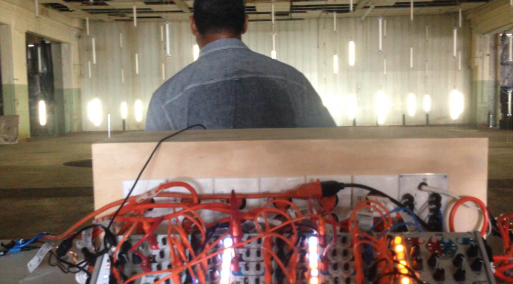
The lights were fluorescent tubes standing vertically in columns in an empty room, 69 lights total. Each column was made of 3 tubes (bottom, middle, top), giving us three layers of lights. The bottom layer was controlled by the kick drum, the middle layer by the snare, the top layer by the hi-hat. Also, the columns were arranged in 4 concentric rings that corresponded to the 4 amplitude bands (loudness response). So there was a center column, then a ring of 6 lights around that, then another ring, and a final perimeter along the edge of the room. A soft tap on the drum would just trigger the inner lights. A medium hit would trigger the center light and one or two rings around that, and a hard hit would turn all the lights on (for that layer only).

Framing the hexagonal matrix

As you might know, fluorescent lights require a ballast, and wiring 69 lights isn’t trivial. Ezra took charge of this project, framing out a ceiling structure to attach each column of lights and to run the wiring overhead, and then taking a few late nights to do the wiring. We used crimp tabs (0.25″ faston style) and solid copper wire and tons of zip ties. It all had to be done very neatly because the audience was invited to walk through the forest of light tubes, and this was to be shown to the sculpture department!

The Show

The performance was at University of Texas’ Sculpture Department in March of 2012. The audience stood facing the light room, and the drummer played in a raised room behind the audience. It was critical that the drummer was watching the lights, and the audience was not watching the drummer. Two different drummers played, with a break in between. I kept my hands near the controls in case a mic slipped or the thresholds needed adjusting. Everything went smoothly, but at the very end of the last drum riff, some of the relays started acting wonky and stuck on. This was clearly because we were using the relays outside of their intended use by flipping them so fast for so long. To prevent such things in the future we would need a budget for industrial grade relays that can handle switching at low audio rates for prolonged periods (around $100 each, times 12 relays…). However, we were lucky this time and it didn’t ruin the show!

The Big Bang Project from Ezra Masch on Vimeo.

The Big Bang Project, debut performance from Ezra Masch

Programming the Pingable Envelope Generator

How to re-program your PEG kit

In a nutshell:

  1. Set up the hardware and software: Updating Firmware on AVR chips
  2. Download the current release of PEG code
  3. Connect ISP to red channel and flash code from your computer (see photo below)
  4. Remove blue channel jumper
  5. Connect ISP to blue channel and flash code from your computer  (see photo below)
  6. Re-install blue channel jumper
  7. Cycle power
  8. Play time!

(see bottom of post for detailed instructions)

Programming the Red channel
Programming the blue channel. Note the blue jumper has been removed so that the 6-pin ISP cable can fit. Replace the jumper after programming, and cycle power before using the PEG.

Detailed Instructions:
First, if don’t already have your computer set up for programming AVR chips, then read the article on programming firmware. You’ll need software installed on your computer (Homebrew+avrdude, AVR Fuses or CrossPack for OSX, or AVRStudio).

Now, remove your PEG from your rack and power it up. You may need a longer ribbon cable, or somehow rig something up so you can keep it powered on while programming.

Next, connect the AVR ISP programmer to the 6-pin header under the red channel chip. Note the red stripe orientation. On your computer, flash the code to the PEG. See photo below.

Next, connect the 6-pin ISP cable to the blue channel header that’s to the right of the blue channel chip. You’ll have to remove the blue jumper from this header, and replace it when you’re done. Flash the code onto the blue channel.

Finally, disconnect the AVR ISP and turn off the PEG, and then turn it back on. This final step is necessary because the jumper on the blue channel is only read at boot-time, so the PEG must be turned off and back on with this jumper installed.

To clear up any confusion, notice that there’s a second blue jumper on the PEG that’s located near the power cable. Just leave this alone during programming. The blue jumper that’s mentioned above is located next to the blue channel AVR chip (towards the top, center of the board).

Technical Note on fuses:

Normally, you won’t have to do anything to the fuses. But if your chips got a static shock, or if you are using brand-new chips from mouser or an electronics supplier (as opposed to chips that you bought from 4ms) then you will need to program the fuses.

With avrdude (which is installed if you have AVRFuses running in OSX) the command is this:

avrdude -F -B 16 -P usb -c avrispmkII -p atmega328p -U hfuse:w:0xd9:m -U lfuse:w:0xce:m

Note that it contains -B 16, which forces avrdude to run at a slower bit-rate since the chips come pre-set at 8Mhz (internal RC osc). When we run this command, we are enabling the external 20MHz ceramic resonator on the PEG pcb, so future commands can be run at a faster bit rate. For example, after executing the above command, we can execute:

avrdude -F -B 0.5 -P usb -c avrispmkII -p atmega328p -U flash:w:peg.hex

(Assuming that the file peg.hex is in the current directory). This runs at -B 0.5 which is must faster!

If you are using AVRStudio, simply type in the following values on the fuses section of the programmer page:

High Fuses: 0xD9

Low Fuse 0xCE

Or, simply go with the default fuse settings, but change the clock settings to Ext. Crystal Res, >8Mhz (fastest), 258 CK/14CK + 4.1ms

Building an RCD Breakout Module

How to make an RCD Breakout

Intro

The Rotating Clock Divider is a Euro-rack format module from 4ms that takes an incoming clock signal and outputs 8 simultaneous divided clocks, each in the range of /1 to /64. It also has a Rotate CV input that re-assigns the divide-amount on the jacks. More information is at 4mspedals.

The RCD features 6 jumpers that can control various features. The User Manual goes into depth about what these do. The breakout panel is a way to bring those jumpers to the front, so you can use flip switches to change the jumper settings on the fly.

For PCB version 1.0.2 and later….

You will need:

  • RCD with PCB 1.0.2 or later (see the bottom for instructions on pcb version 1.0.1 and 1.0)
  • 4HP panel
  • 6 SPST switches
  • 16-conductor cable with a 2×8 connector on one end (standard Doepfer power cable, cut in half).

Here’s how it goes together in a nutshell:

PCB 1.0.2 RCDBO

Let’s start by looking at the connection to the board. There’s only 12 pins on the board, but the connector has 16 holes. That’s OK! Just let the bottom four holes hang off (those four wires don’t go to anything anyways, as you can see in the first diagram). To be clear, by the “bottom four holes” I mean the four holes on the right hand side in the photo below (they are on the bottom in the photo above). The edge of the connector should not stick over the edge of the board.

Cable connection to RCD board -- Click to enlarge

OK, now let’s look at the wiring of the panel. There are six switches, each has two connections.

Notice the Max Divide 1 and 2 switches are flipped from the other 4 switches: the lugs are on the right side. That’s just because of the way I labeled the panel (which is the same one included in the 4ms kit, so do it exactly like this if you got the panel in the kit). For the top two switches, flipping the switch lever to the left will open the connection (same as removing the jumper) and flipping it to the right will close the connection (same as putting on the jumper). For the bottom 4 switches, flipping the switch to the right is like removing the jumper, flipping to the left is like installing the jumper. See the User Manualfor a description of what the jumpers do!


PCB version 1.0.1 (and 1.0)

For PCB version 1.0.1, it’s the same process, but the switches are in a different order. Using the same cable above, it goes:

1 (Red) & 2: Max Div 32
3 & 4: Max Div 16
5 & 6: Spread
7 & 8: Auto-Reset
9 & 10: Counting
11 & 12: Gate/Trig
13-16: not used

RCD PCB 1.0.1 wiring to RCDBO

Obviously you will have to upgrade your chip firmware to v1.1 if you want to use Gate/Trig or Up/Down counting or Spread. You can read about upgrading on the RCD page on 4mspedals.com

PCB version 1.0

For PCB 1.0, there’s only 4 switches hard-wired to the breakout connector pins, so you have to solder wires from the back of the PCB to some jumper pins which you insert into the breakout’s connector. Look at the photo:

PCB 1.0, solder the three wires to the 4-pin connector

You will be soldering the red, yellow, and black wires from the PCB to the back of a 4-pin (2×2) connector. Note that the black wire connects to BOTH pins in a row, but the red and yellow wires connect to one pin each. The inset photo shows the back of the 4-pin connector.

To use your new 4-pin, just push it into the breakout’s 16-pin connector where the Up/Down and Gate/Trig jumpers are supposed to go. Follow the pin numbering from the PCB 1.0.1 section (above). The red wire is Up/Down and that should be closest to the existing breakout pins. The yellow wire is next to the red, farthest from the existing pins. The black wires should be on the top.

Updating firmware on AVR chips

A number of 4ms devices use an AVR microcontroller. These chips run a small program. On most 4ms devices that use an AVR chip, there’s a 6-pin header (2 rows of 3 pins) near the chip. This header lets you update, upgrade, or hack the AVR chip.

Here’s how to do it:

You will need…

  1. AVR ISP mk2
    AVR ISP mk2

    ISP (In-circuit Programmer): I recommend the AVRISP2 (also known as AVR ISP MKII) available from atmel.com, or Mouser for $34, or ebay and amazon sometimes. In Europe, try Farnell

  2. A computer with a USB port. Windows actually has the most seamless installer, but I also use Mac and Linux to burn code. Download and install one of these:
    • Windows: AVR Studio 4.19. Download it here: AVR Studio Archives. (Note that the latest version is AVR Studio 6, which will probably work, but these instructions are geared for AVR Studio 4)
    • Mac OS X:
      • Method 1: Install homebrew by following this guide (a one-line installation). Then type “brew install avrdude” into the Terminal and press enter. Then you can install AVRFuses (see below for how to set the AVR Fuses preferences)
      • Method 2: Download and install Crosspack-AVR and then AVRFuses
    • Linux: You just need the avrdude program to burn code, but can install the whole avr-gcc toolchain if you might be compiling your own firmware.
  3. The hex file: This is the actual file that contains the firmware update. If you’re upgrading a device, this will be available for download on the device’s web page, or you can find alternative firmwares on the 4ms github. If you’re an advanced hacker, you’ll probably compile your own code using avr-gcc (part of AVR Studio and Crosspack) which will generate a hex file for you. The file should be in intel hex format, ending in .hex

Specific instructions for PEG:

If you’re programming a PEG, read this article specifically about the PEG before continuing.

Click the image for instructions specific to the PEG

Specific instructions for QCD:

The QCD has four ATtiny85 chips: one for the tap button and one for each of the four channels. Each chip has its own 6-pin ISP header.

The tap button chip can be programmed normally. It’s marked with a white dot and is located under the tap button and jack. (At this time, the firmware for the tap button is not available)

To program the channels, you must apply a gate signal to the Reset and CLK IN jack for the channel you’re programming. The gate signal should be 5V or more. Note: It’s usually fine to use a passive mult to split one gate signal to all the Reset and CLK IN jacks.

Specific instructions for QPLFO:

The QPLFO has four ATtiny85 chips: one for each channel. Each chip has its own 6-pin ISP header.

To program the channels, you must apply a gate signal to the Reset and Ping jack for the channel you’re programming. The gate signal should be 5V or more. Note: It’s usually fine to use a passive mult to split one gate signal to all the Reset and Ping jacks.


Detailed Instructions:

PLuig the AVR ISP mkII into the 6-pin header of your device, making sure to line the red stripe up with the printed white box on the PCB

Windows (AVR Studio 4):

  1. Download and installAVR Studio 4.19 from the AVR Studio Archives. 
  2. Run the installer and click OK/Next to everything. Yes, you want the “Jungo/USB” driver to be installed.
  3. Plug in your AVR ISP mkII into the USB port and make sure Windows finds it, and automatically installs the drivers. The green light near the USB plug should come on.
  4. Power your device up (that is, plug your Rotating Clock Divider into your Eurorack system, or power up your Bend Matrix, etc…). Your device should be running normally, but don’t plug any patch cables into it
  5. Plug the 6-pin ISP header of the AVRISP mkII into your device. Note the orientation: the red stripe should go towards the white box that’s printed on the PCB: see photo above.
  6. The light near the 6-pin cable on the AVRISP mkII should turn green, indicating that it detects power. If you plugged it in backwards, it might flash orange. Nothing’s damaged, just flip it around…
  7. Run AVRStudio 4
  8. Click the little “AVR Programmer” icon: AVR Programmer
  9. If it doesn’t automatically detect your AVR ISP mkII, then select it from the box on the left, and click “USB”, and then click “Connect…”
  10. Click on the “Main” tab, and select “ISP mode” from the bottom box. Click “Settings” and choose an ISP Frequency of 125kHz.
  11. Select the chip you’re programming under “Device and Signature Bytes”:
    • Select “ATmega168” for the RCD or SCM
    • ATtiny84 for the Auto Bass Gen
    • ATmega32 for the Bend Matrix
    • ATmega328 for the PEG
    • ATtiny85 for the QPLFO or QCD channels
    • ATtiny2313 for the QPLFO tap controller
  12. Click “Read Signature” and it should say “Signature matches device”
  13. Click the “Program” tab. Under “Flash” click the “…” button next to “Input HEX File” (the top one). Make sure you’re not under EEPROM! Select your hex file that you downloaded (or compiled yourself)
  14. Now, click “Program” (under the Flash section, not under the EEPROM section). It should give you no errors at the bottom of the window
  15. Unplug your ISP 6-pin header and you should be good to go!

Please let me know if you have any problems!

Mac OSX (AVR Fuses) –the easy way to upgrade your firmware:

Method 1: Install homebrew by opening up Terminal and typing:


ruby -e "$(curl -fsSL https://raw.githubusercontent.com/Homebrew/install/master/install)"

(all on one line). Then press enter. When it’s done, type:

  1. brew install avrdude

    and press enter.
    Or… do Method 2: Download and install Crosspack-AVR

  1. Download and install AVR Fuses.
  2. Select File->Preferences in AVR Fuses.
    1. Set the location of avrdude (it probably will be /usr/local/bin/avrdude).
    2. Set Programmer to “avrispmkII”
    3. Set Port to usb
    4. Set Bit Clock to 8
  3. Download the hex file for your upgrade from 4mspedals.com
  4. Plug in your AVR ISP mkII. The green light by the USB plug might not come on.
  5. Do steps 4, 5, and 6 of the Windows installation (power up your device, plug in the AVR ISP mkII, make sure the green light comes on)
  6. Open up AVR Fuses.
  7. Select the AVR chip type that you’re using (the name of the chip is also printed on the chip itself, use a flashlight to read the tiny letters!)
  8. Pingable Envelope Generator (PEG) uses ATMEGA328
    Bend Matrix uses ATMEGA32 or ATMEGA32A
    RCD and SCM: ATMEGA168 or ATMEGA168P
    AutoBassGen: ATTINY84
  9. Select the hex file you downlaoded in step 2, and burn it onto your chip!

Mac OSX (Crosspack) –the advanced way to hack your code:

  1. Download and install Crosspack from here: http://www.obdev.at/products/crosspack/index.html]
  2. Download the hex file for your upgrade. Save the file in your Home directory, so you can find it easily with the Terminal.
  3. Plug in your AVR ISP mkII. The green light by the USB plug might not come on.
  4. Do steps 4, 5, and 6 of the Windows installation (power up your device, plug in the AVR ISP mkII, make sure the green light comes on)
  5. Open up your Terminal program (in Utilities folder)
  6. In Terminal, type “ls” and hit enter. You should see the name of the hex file that you saved in your Home directory (along with everything else in your Home directory). If not, you didn’t save it in the right place.
  7. Now tell it to burn the code. For the RCD, type this command (all on one line)
    avrdude -P usb -c avrispmkII -p atmega168  -U flash:w:clocker.hex -v -v

    And press enter. This assumes your hex file is named “clocker.hex”. It should say “avrdude: Thank you” and have no errors above that. If all goes well, unplug your 6-pin cable and your RCD is updated!

    If you’re using a fresh chip, you’ll need to use this command to burn the fuses:

    avrdude -P usb -c avrispmkII -p atmega168 -U hfuse:w:0xd7:m -U lfuse:w:0xef:m -U efuse:w:0x01:m -U flash:w:clocker.hex

Linux:

  1. Install avrdude. You can probably install it with your package manager, such as Aptitude: (type “sudo aptitude install avrdude”), or Ubuntu’s Synaptic
  2. Follow the OSX instructions starting at step 2. Hint, if avrdude is not finding a usb connection, you might need to type “sudo” before the avrdude commands. Then it’ll ask you for your password before running avrdude.

Solar Pump display panel design

4435547099_cb89302c52_b
Solar charging station at the Austin fire station Trinity/4th

Sol Design Lab’s Solar Pump, a solar-powered charging station for mobile electronics, was an official part of South-by-Southwest this year. The stations have standard outlets, so anyone can walk up and charge a cell phone, laptop, or even an electric bike or scooter. The power comes from solar panels on the roof of the stations, so there’s no charge for charging (sorry… couldn’t resist). Refurbished 1950’s gas pumps provide a retro-future look that catch the public’s eye and twists the concept of “fill-up station”.

We set up three stations throughout Austin, including a large station downtown by the convention center, a smaller “pump” outside the South Lamar Alamo theater, and a mobile “pump” at Auditorium Shores. The Solar Pump grew out of Beth Ferguson’s MFA project, and these represent the third generation of prototypes.

LED display panel
LED display panel

My main role was the design and construction of the digital display, which used LEDs to indicate solar panel voltage, power output (to the inverter) and battery bank voltage. More technical details below….

Each station is a little bit different, with either 2 or 4 deep cycle 100AH 12V batteries creating a 24V system. A 1100W inverter supplies standard 110VAC power to the user through a GFCI outlet (including a big red Emergency-Stop button!). Between 2 and 4 bi-facial Sanyo solar panels charge the batteries through a Morningstar charge controller. We used the Pentametrix system to read the shunts and voltages, and then send that data digitally over RS-232 to the custom digital display module.

Solar charging station at the Austin fire station Trinity/4th

solarpump
Solar Pump at Alamo Drafthouse, South Lamar

Tech details

Here’s the schematic:


Front panel schematic


Here’s the code (avr-gcc, using AVR Studio 4): solarpumppanel.c

Software

An Atmel AVR ATmega32A chip is at the core, communicating with the Pentametrix meter over a serial cable. The AVR makes a “request” to the Pentametrix every 500mS or so, and the Pentametrix responds with the latest readings: voltage on the solar panels, voltage on the battery bank, and current flowing out of the batteries to the inverter. The AVR then scales and converts these numbers and outputs them to the LED displays. The UART runs at 2400 baud, and the final byte is a checksum. If the checksum is off, or if the AVR doens’t hear a response from the Pentametrix, an error light goes on inside the box. Not terribly useful for debugging on the field, but on the bench this was handy.

Hardware

A Max232 chip handles the RS232 voltages, converting RS232 levels (-7V/+7V) to/from TTL levels (0V/5V). This directly connects to the AVR’s UART pins (RX/TX). These chips rule, they are totally worth the cost and board space.

Driving the LED displays turned out to be a little harder than I originally thought because the super-bright displays we found drop 7.4V, which is obviously higher than the 5V the AVR chip runs on. So I had to use an NPN/PNP transistor pair for each blue LED digit to switch +9V. (Q4/Q4B, Q5/Q5B, Q6/Q6B). This turned out to work well once I became OK with modifying the PCB and changing the code invert the “on” and “off” signals on the AVR pins for the blue digits only.

The yellow digits drop much less voltage, so I ran them on +5V and only needed on PNP transistor per digit (Q1, Q2, Q3). I’ve used the 2N5401 PNP transistor with good results for switching LED segments in other projects, and also have seen it around in the Peggy project… it’s fast and can drop a good amount of power… a keeper.

Finally, there’s a “bar graph” LED display which is 5 sets of LEDs, with 4 LEDs in parallel in each set. Each LED set is a different type of LED so they have a trimpot to set their brightness. I used the same 2N5401 PNP transistor on a 5V rail for these.

I went super-conservative on the powersupply, dropping the original 24V down to 18V, then to 9V, then to 5V.

Oh did I mention I found Pink LEDs! Yeah!!

Enclosure

Beth and drew up the front panel graphics in Illustrator, and I sheared some panels from 2mm aluminum. I then took that to a friend with a mill, who cut the rectangular holes for the numerical displays. I drilled out the round holes figured out a (perhaps excessively elaborate) way to mount the PCB to the front panel, and bend a flanged box to shield the circuit from the rear. The front panel is the main structural element and is mounted to braces which mounted to the frame of the pump.

I powdercoated the front panels white, and then applied the graphics with a decal, and baked that on. It came out pretty nice!