Category Archives: AVR chips

Programming the Pingable Envelope Generator

How to re-program your PEG kit

In a nutshell:

  1. Set up the hardware and software: Updating Firmware on AVR chips
  2. Download the current release of PEG code
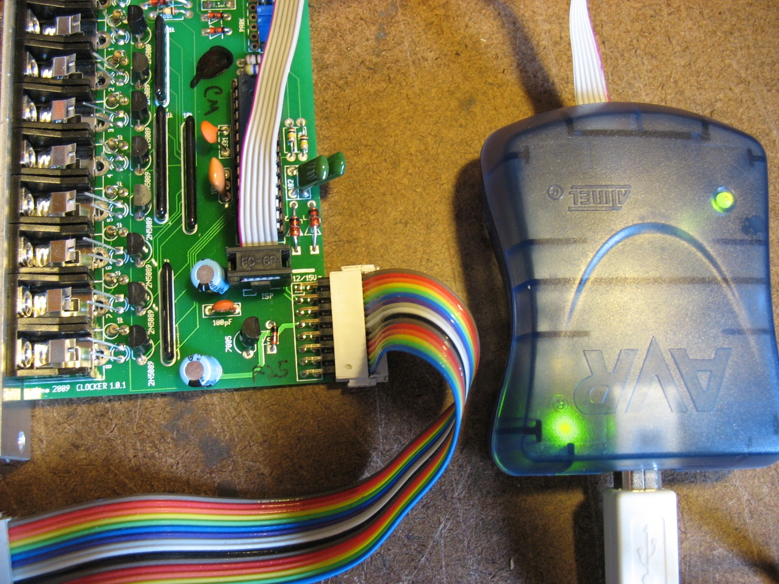
  3. Connect ISP to red channel and flash code from your computer (see photo below)
  4. Remove blue channel jumper
  5. Connect ISP to blue channel and flash code from your computer  (see photo below)
  6. Re-install blue channel jumper
  7. Cycle power
  8. Play time!

(see bottom of post for detailed instructions)

Programming the Red channel
Programming the blue channel. Note the blue jumper has been removed so that the 6-pin ISP cable can fit. Replace the jumper after programming, and cycle power before using the PEG.

Detailed Instructions:
First, if don’t already have your computer set up for programming AVR chips, then read the article on programming firmware. You’ll need software installed on your computer (Homebrew+avrdude, AVR Fuses or CrossPack for OSX, or AVRStudio).

Now, remove your PEG from your rack and power it up. You may need a longer ribbon cable, or somehow rig something up so you can keep it powered on while programming.

Next, connect the AVR ISP programmer to the 6-pin header under the red channel chip. Note the red stripe orientation. On your computer, flash the code to the PEG. See photo below.

Next, connect the 6-pin ISP cable to the blue channel header that’s to the right of the blue channel chip. You’ll have to remove the blue jumper from this header, and replace it when you’re done. Flash the code onto the blue channel.

Finally, disconnect the AVR ISP and turn off the PEG, and then turn it back on. This final step is necessary because the jumper on the blue channel is only read at boot-time, so the PEG must be turned off and back on with this jumper installed.

To clear up any confusion, notice that there’s a second blue jumper on the PEG that’s located near the power cable. Just leave this alone during programming. The blue jumper that’s mentioned above is located next to the blue channel AVR chip (towards the top, center of the board).

Technical Note on fuses:

Normally, you won’t have to do anything to the fuses. But if your chips got a static shock, or if you are using brand-new chips from mouser or an electronics supplier (as opposed to chips that you bought from 4ms) then you will need to program the fuses.

With avrdude (which is installed if you have AVRFuses running in OSX) the command is this:

avrdude -F -B 16 -P usb -c avrispmkII -p atmega328p -U hfuse:w:0xd9:m -U lfuse:w:0xce:m

Note that it contains -B 16, which forces avrdude to run at a slower bit-rate since the chips come pre-set at 8Mhz (internal RC osc). When we run this command, we are enabling the external 20MHz ceramic resonator on the PEG pcb, so future commands can be run at a faster bit rate. For example, after executing the above command, we can execute:

avrdude -F -B 0.5 -P usb -c avrispmkII -p atmega328p -U flash:w:peg.hex

(Assuming that the file peg.hex is in the current directory). This runs at -B 0.5 which is must faster!

If you are using AVRStudio, simply type in the following values on the fuses section of the programmer page:

High Fuses: 0xD9

Low Fuse 0xCE

Or, simply go with the default fuse settings, but change the clock settings to Ext. Crystal Res, >8Mhz (fastest), 258 CK/14CK + 4.1ms

Updating firmware on AVR chips

A number of 4ms devices use an AVR microcontroller. These chips run a small program. On most 4ms devices that use an AVR chip, there’s a 6-pin header (2 rows of 3 pins) near the chip. This header lets you update, upgrade, or hack the AVR chip.

Here’s how to do it:

You will need…

  1. AVR ISP mk2
    AVR ISP mk2

    ISP (In-circuit Programmer): I recommend the AVRISP2 (also known as AVR ISP MKII) available from atmel.com, or Mouser for $34, or ebay and amazon sometimes. In Europe, try Farnell

  2. A computer with a USB port. Windows actually has the most seamless installer, but I also use Mac and Linux to burn code. Download and install one of these:
    • Windows: AVR Studio 4.19. Download it here: AVR Studio Archives. (Note that the latest version is AVR Studio 6, which will probably work, but these instructions are geared for AVR Studio 4)
    • Mac OS X:
      • Method 1: Install homebrew by following this guide (a one-line installation). Then type “brew install avrdude” into the Terminal and press enter. Then you can install AVRFuses (see below for how to set the AVR Fuses preferences)
      • Method 2: Download and install Crosspack-AVR and then AVRFuses
    • Linux: You just need the avrdude program to burn code, but can install the whole avr-gcc toolchain if you might be compiling your own firmware.
  3. The hex file: This is the actual file that contains the firmware update. If you’re upgrading a device, this will be available for download on the device’s web page, or you can find alternative firmwares on the 4ms github. If you’re an advanced hacker, you’ll probably compile your own code using avr-gcc (part of AVR Studio and Crosspack) which will generate a hex file for you. The file should be in intel hex format, ending in .hex

Specific instructions for PEG:

If you’re programming a PEG, read this article specifically about the PEG before continuing.

Click the image for instructions specific to the PEG

Specific instructions for QCD:

The QCD has four ATtiny85 chips: one for the tap button and one for each of the four channels. Each chip has its own 6-pin ISP header.

The tap button chip can be programmed normally. It’s marked with a white dot and is located under the tap button and jack. (At this time, the firmware for the tap button is not available)

To program the channels, you must apply a gate signal to the Reset and CLK IN jack for the channel you’re programming. The gate signal should be 5V or more. Note: It’s usually fine to use a passive mult to split one gate signal to all the Reset and CLK IN jacks.

Specific instructions for QPLFO:

The QPLFO has four ATtiny85 chips: one for each channel. Each chip has its own 6-pin ISP header.

To program the channels, you must apply a gate signal to the Reset and Ping jack for the channel you’re programming. The gate signal should be 5V or more. Note: It’s usually fine to use a passive mult to split one gate signal to all the Reset and Ping jacks.


Detailed Instructions:

PLuig the AVR ISP mkII into the 6-pin header of your device, making sure to line the red stripe up with the printed white box on the PCB

Windows (AVR Studio 4):

  1. Download and installAVR Studio 4.19 from the AVR Studio Archives. 
  2. Run the installer and click OK/Next to everything. Yes, you want the “Jungo/USB” driver to be installed.
  3. Plug in your AVR ISP mkII into the USB port and make sure Windows finds it, and automatically installs the drivers. The green light near the USB plug should come on.
  4. Power your device up (that is, plug your Rotating Clock Divider into your Eurorack system, or power up your Bend Matrix, etc…). Your device should be running normally, but don’t plug any patch cables into it
  5. Plug the 6-pin ISP header of the AVRISP mkII into your device. Note the orientation: the red stripe should go towards the white box that’s printed on the PCB: see photo above.
  6. The light near the 6-pin cable on the AVRISP mkII should turn green, indicating that it detects power. If you plugged it in backwards, it might flash orange. Nothing’s damaged, just flip it around…
  7. Run AVRStudio 4
  8. Click the little “AVR Programmer” icon: AVR Programmer
  9. If it doesn’t automatically detect your AVR ISP mkII, then select it from the box on the left, and click “USB”, and then click “Connect…”
  10. Click on the “Main” tab, and select “ISP mode” from the bottom box. Click “Settings” and choose an ISP Frequency of 125kHz.
  11. Select the chip you’re programming under “Device and Signature Bytes”:
    • Select “ATmega168” for the RCD or SCM
    • ATtiny84 for the Auto Bass Gen
    • ATmega32 for the Bend Matrix
    • ATmega328 for the PEG
    • ATtiny85 for the QPLFO or QCD channels
    • ATtiny2313 for the QPLFO tap controller
  12. Click “Read Signature” and it should say “Signature matches device”
  13. Click the “Program” tab. Under “Flash” click the “…” button next to “Input HEX File” (the top one). Make sure you’re not under EEPROM! Select your hex file that you downloaded (or compiled yourself)
  14. Now, click “Program” (under the Flash section, not under the EEPROM section). It should give you no errors at the bottom of the window
  15. Unplug your ISP 6-pin header and you should be good to go!

Please let me know if you have any problems!

Mac OSX (AVR Fuses) –the easy way to upgrade your firmware:

Method 1: Install homebrew by opening up Terminal and typing:


ruby -e "$(curl -fsSL https://raw.githubusercontent.com/Homebrew/install/master/install)"

(all on one line). Then press enter. When it’s done, type:

  1. brew install avrdude

    and press enter.
    Or… do Method 2: Download and install Crosspack-AVR

  1. Download and install AVR Fuses.
  2. Select File->Preferences in AVR Fuses.
    1. Set the location of avrdude (it probably will be /usr/local/bin/avrdude).
    2. Set Programmer to “avrispmkII”
    3. Set Port to usb
    4. Set Bit Clock to 8
  3. Download the hex file for your upgrade from 4mspedals.com
  4. Plug in your AVR ISP mkII. The green light by the USB plug might not come on.
  5. Do steps 4, 5, and 6 of the Windows installation (power up your device, plug in the AVR ISP mkII, make sure the green light comes on)
  6. Open up AVR Fuses.
  7. Select the AVR chip type that you’re using (the name of the chip is also printed on the chip itself, use a flashlight to read the tiny letters!)
  8. Pingable Envelope Generator (PEG) uses ATMEGA328
    Bend Matrix uses ATMEGA32 or ATMEGA32A
    RCD and SCM: ATMEGA168 or ATMEGA168P
    AutoBassGen: ATTINY84
  9. Select the hex file you downlaoded in step 2, and burn it onto your chip!

Mac OSX (Crosspack) –the advanced way to hack your code:

  1. Download and install Crosspack from here: http://www.obdev.at/products/crosspack/index.html]
  2. Download the hex file for your upgrade. Save the file in your Home directory, so you can find it easily with the Terminal.
  3. Plug in your AVR ISP mkII. The green light by the USB plug might not come on.
  4. Do steps 4, 5, and 6 of the Windows installation (power up your device, plug in the AVR ISP mkII, make sure the green light comes on)
  5. Open up your Terminal program (in Utilities folder)
  6. In Terminal, type “ls” and hit enter. You should see the name of the hex file that you saved in your Home directory (along with everything else in your Home directory). If not, you didn’t save it in the right place.
  7. Now tell it to burn the code. For the RCD, type this command (all on one line)
    avrdude -P usb -c avrispmkII -p atmega168  -U flash:w:clocker.hex -v -v

    And press enter. This assumes your hex file is named “clocker.hex”. It should say “avrdude: Thank you” and have no errors above that. If all goes well, unplug your 6-pin cable and your RCD is updated!

    If you’re using a fresh chip, you’ll need to use this command to burn the fuses:

    avrdude -P usb -c avrispmkII -p atmega168 -U hfuse:w:0xd7:m -U lfuse:w:0xef:m -U efuse:w:0x01:m -U flash:w:clocker.hex

Linux:

  1. Install avrdude. You can probably install it with your package manager, such as Aptitude: (type “sudo aptitude install avrdude”), or Ubuntu’s Synaptic
  2. Follow the OSX instructions starting at step 2. Hint, if avrdude is not finding a usb connection, you might need to type “sudo” before the avrdude commands. Then it’ll ask you for your password before running avrdude.

SimSam

SimSam 1.0

Unveiled at the beginner’s class at Handmade Music Austin #4, the SimSam (Simple Sampler) is a single-chip “sample-rate cruncher” that’s glitchy as all-get-out but only costs about $8-$12 in parts. It’s an effect with an input and output jack; and it’s a noise-maker since a jumper shorts the output back into the input when nothing is plugged into the input jack. We built 28 SimSams in a couple hours at the workshop.

Update: SimSam 2.0

SimSam 2.0 is an improved version that runs the same code as v1.0 (thus has the same functionality), but adds a Reset button. This button is on the left. The other two buttons are the same as SimSam v1.0. Also, on the PCB v2.0 there is a spot for a fourth button underneath the middle button. This is not used and only for testing/hacking your own firmware. Really, it will do nothing (except possibly damage the chip) if you install a button here, so don’t think about it. The code uses it as an output, low when the code is initializing and high when it’s running.
Continue reading SimSam