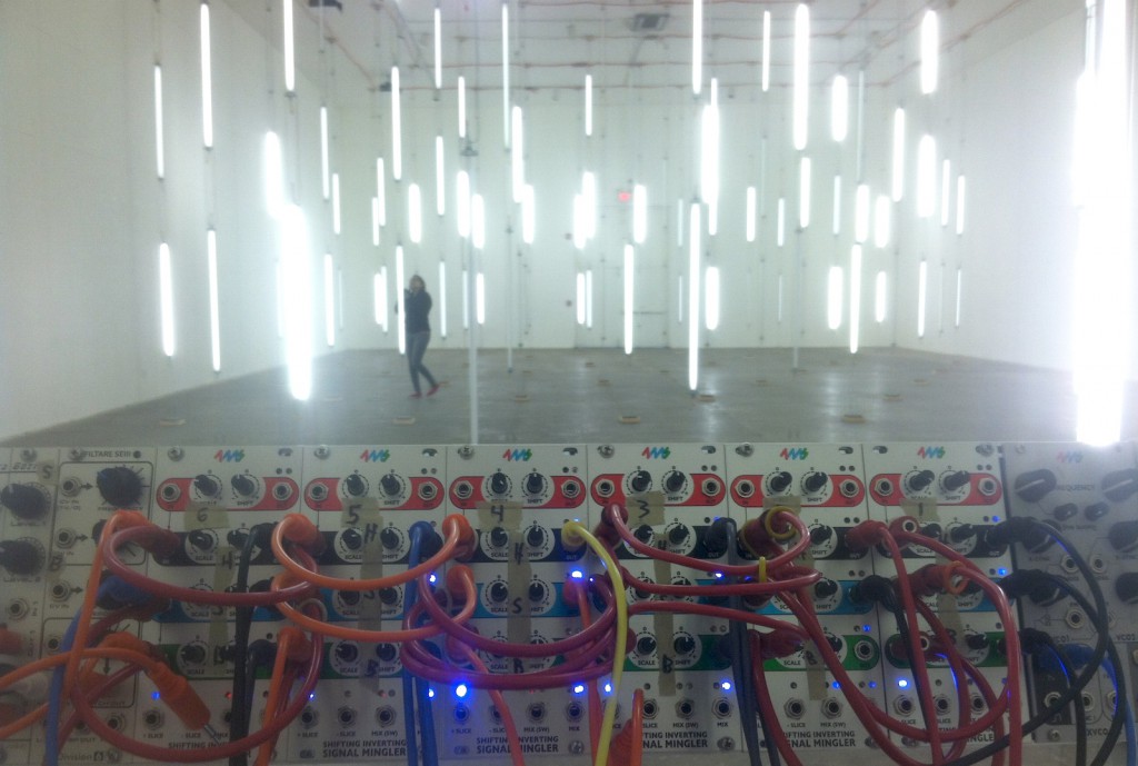
A Matrix of 183 Fluorescent Light Tubes Controlled by a Live Drummer
Read about the first two installations on this blog:
First installation: March 2012 at the University of Texas in Austin
Second installation: June 2014 at Forcefield Project in Philadelphia
Third installation: December 2014 at Crane Arts Center, Ice Box room in Philadelphia
In December 2014, Ezra raised funds through a kickstarter to pay for a 3rd installation of the Light Room (aka Big Bang Project aka Drum Triggered Room of Lights). This time it would be bigger than every (twice as many lights) and be open to the public in a well-know art gallery. Ezra, Rinda, and a bunch of volunteers did the wiring, and I flew out to Philly a week before the show to set up the low-voltage circuitry, calibrate the system, and troubleshoot problems.
System overview

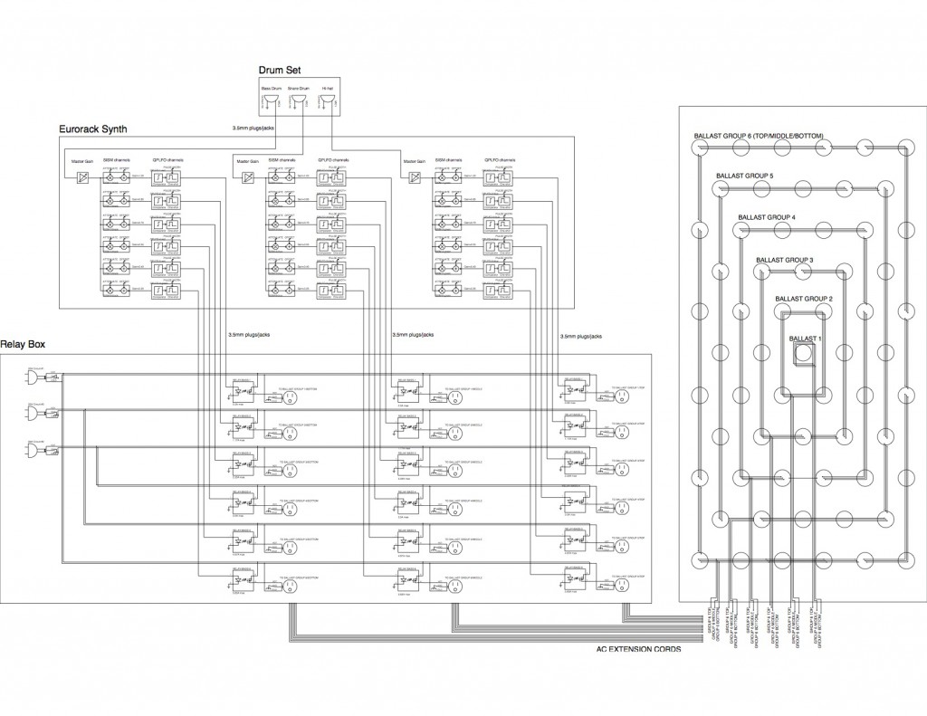
Take a look at the diagram above, it shows the basic components that we used to control the lights with the drums.
In a nut-shell:
Each drum gets a microphone. Each mic is split into six channels. Each channel controls a relay. Each relay controls a group of lights. There’s 3 drums, 18 channels, 183 lights.
In a slightly larger nut-shell:
When a drum is struck, the contact microphone sends a signal to the synth. This is amplified by the pre-amp and then split into six channels. Each channel has a Level Set (a volume knob), which determines how much signal needs to be present on the mic before triggering the next stage, the Pulse Generator. The Pulse Generator cleans up the analog mic signal with a comparator, and then outputs one clean pulse every time the threshold is crossed. The more that each channel’s level is turned down with the Level Set, the harder the drum has to be hit to make the Pulse Generator fire. Thus we’ve created six amplitude bands. Finally, the Pulse Generator’s output is sent to an AC relay, which turns on a 120VAC circuit that powers one or more ballasts. Each ballast powers up to four lights.
Pulse Width
A cool thing about the one-shot inside the Pulse Generator is that we can control the pulse width. The pulse width determines how long each group of lights will stay on once it’s triggered. This means if we hit the drum at maximum strength, all the lights will go on at about the same time, but they can turn off at different times based on each of their pulse width settings. We used this technique to create animation effects such as making the lights seem to collapse into the center of the room.
The verbose explanation:
Below is a diagram of the entire circuit, from drum set to lights. We’ll break it down section by section:
Drum Set
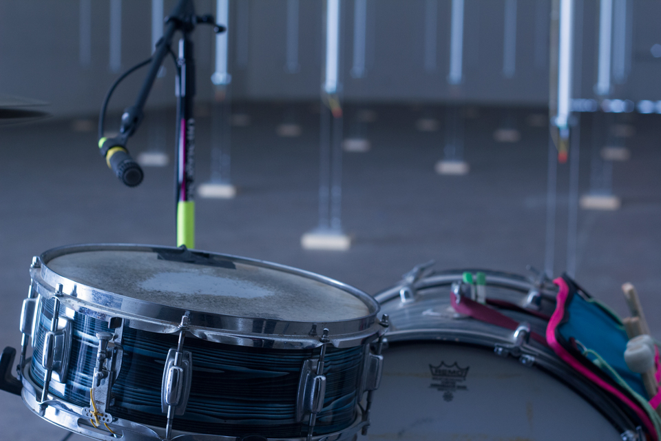 We had a simple drum kit: kick, snare, hi-hat. Each of the three drums had a contact mic taped to their resonating surface. The mics then ran to the next section, the synth…

Low-voltage processing: The Synth
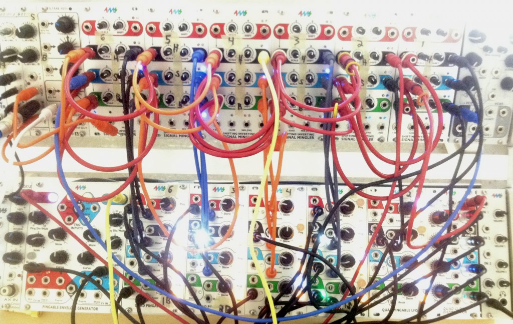
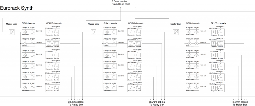
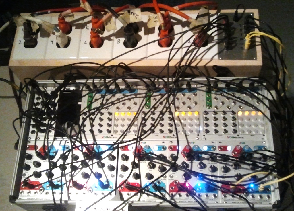
The synth was built from off-the-shelf eurorack modules: 4ms QPLFO, 4ms SISM, Circuit Abbey Gozinta, and Division 6 Filtaire. I loaded some custom firmware onto the QPLFO to make it only output pulses and always operate in one-shot mode. Since I work at 4ms Company, I have access to lots of 4ms modules, so I used them as much as possible!
The Master Gain (preamp) modules were Gozintas. I used six SISMs for the Attenuate/Offset function, leaving the red (top) channel of each module open. Then I used five QPLFOs for the Pilse Generators (comparator/one-shots). The QPLFOs had firmware running that caused them to generate a pulse wave when receiving a trigger on the Reset jack. This is the same as the QPLFO’s normal “one-shot” mode, except it outputs a square wave instead of a triangle/saw/ramp. Also, giving it a clock won’t pull it out of one-shot mode. I could adjust the pulse width via the Skew knob and by tapping a tempo on the Ping button. I could also mute a channel with the Mute button.
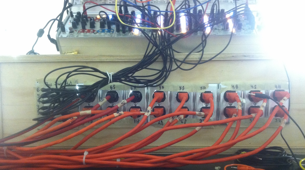
The outputs of the QPLFO channels went to the Relay Box, via 1/8″ cables.
High-voltage: Relays

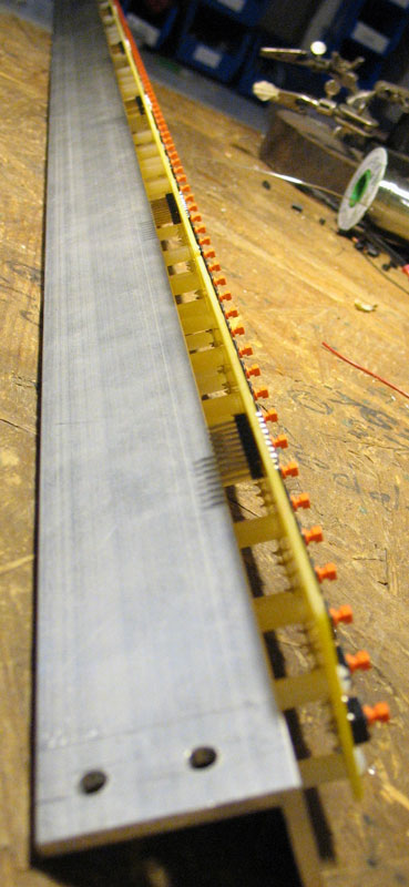
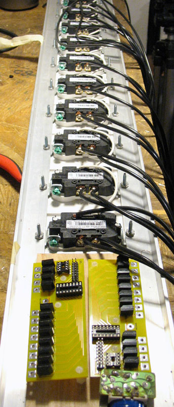
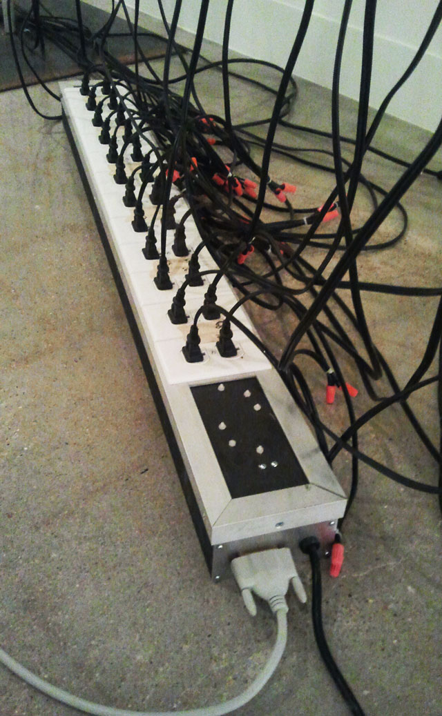
The Relay Box has 18 low-voltage inputs (3.5mm jacks) and 18 high-voltage outputs (120VAC outlets). It also has three standard AC wall plugs (20A) that provide power to the outlets when the corresponding relay is turned on by the low voltage inputs.

Inside the box are 18 relays, the G3NA-210B by Omron. These are solid-state relays, which is crucial because we’re switching at audio rates. Ordinary electro-mechanical relays fail at these rates (we learned this the hard way on our first installation!). Another critical parameter of the relay is the 5V-24VDC input. Since the synth outputs 5V DC, we can directly trigger the relays from the synth and don’t need any level conversion. These relays can handle up to 10A if heatsinked properly, and 4A with no heatsink.
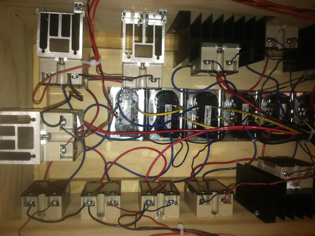 The wiring was straightforward: each 3.5mm jack was wired directly to the input on a relay. One terminal on the output side of each relay was wired to an outlet, and the other terminal was wired to the hot line of the incoming AC. The cold line of the incoming AC was wired directly to the other side of the outlet.
Six of the relays controlled four or more ballasts, and each ballast required about 1.17A (4 x 32W bulbs x 1.1 efficiency rating = 120VAC x 1.17A). Thus, these six relays needed to be heatsinked because they would be loaded with over 4A (4 x 1.17A > 4A). We used large heatsinks which allowed for up to 10A (more than enough). Another three heatsinks powered three ballasts each (12 bulbs) which is close to the maximum of 4A. Rather than push the limit, I decided to heatsink these three relays with smaller heatsinks. The final nine relays powered less than 12 bulbs each, so they had less than 4A passing through them at any given time, and therefore did not need a heatsink.
Coming out of the relay box were 18 extension cords, which we attached to the wall and ran along the ceiling to the ballasts.
Display: The Lights
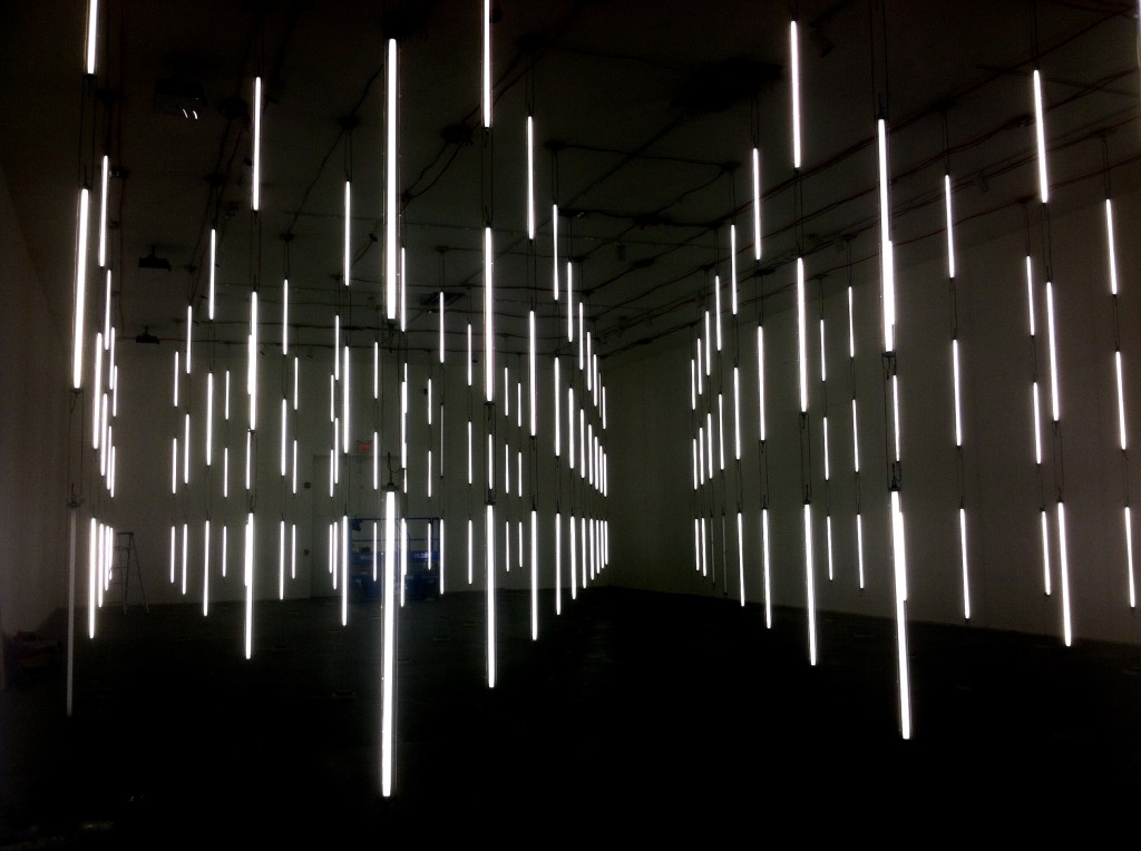
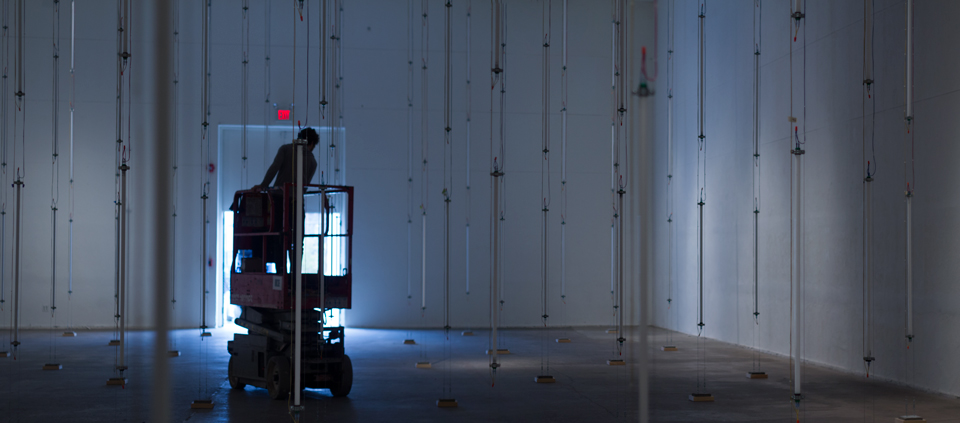
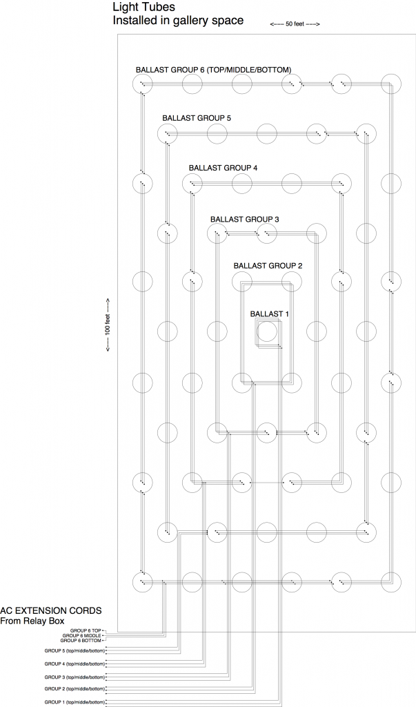
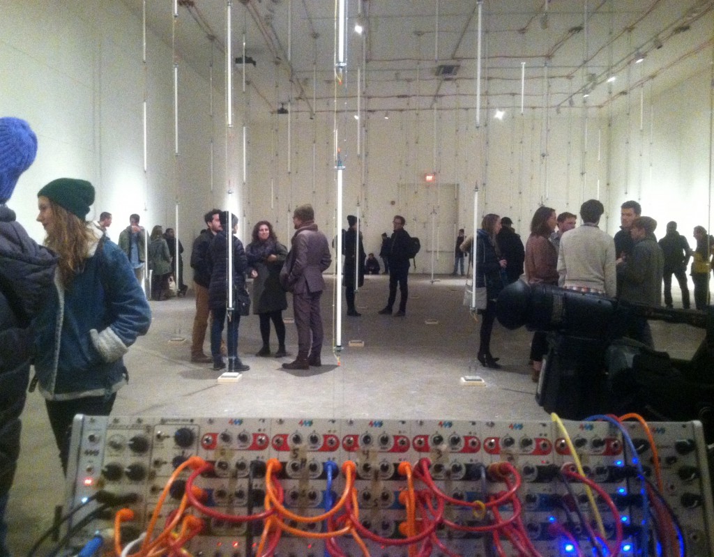
The lights were arranged in groups and layers. Look at the room layout drawing above. Each circle is a column of three lights (low, middle high). There are also six groups, each of which is a concentric rectangles, including the center light. The outer rectangle is called Group 6, the next is called Group 5, etc… and the center light is called Group 1. Each of the six groups exists on three layers (hi-hat, snare, or bass), so in total we have 18 groups.
The fluorescent tubes are powered by ballasts. Each ballasts powered four lights each, except the three Group 1 ballasts powered a single bulb each. For Group 6, which has 20 lights, we used five ballasts. The AC inlets of these five ballasts were tied together and one long extension cord ran back to the relay box. Each of the 18 groups was wired like that, so we had 18 extension cords running along the ceiling. In total there were 45 quad-bulb ballasts and 3 single-bulb ballasts.
Floating columns of light
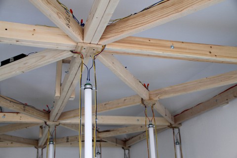
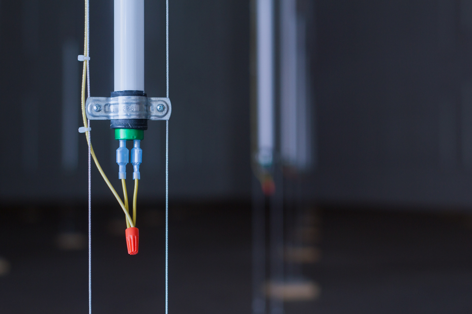
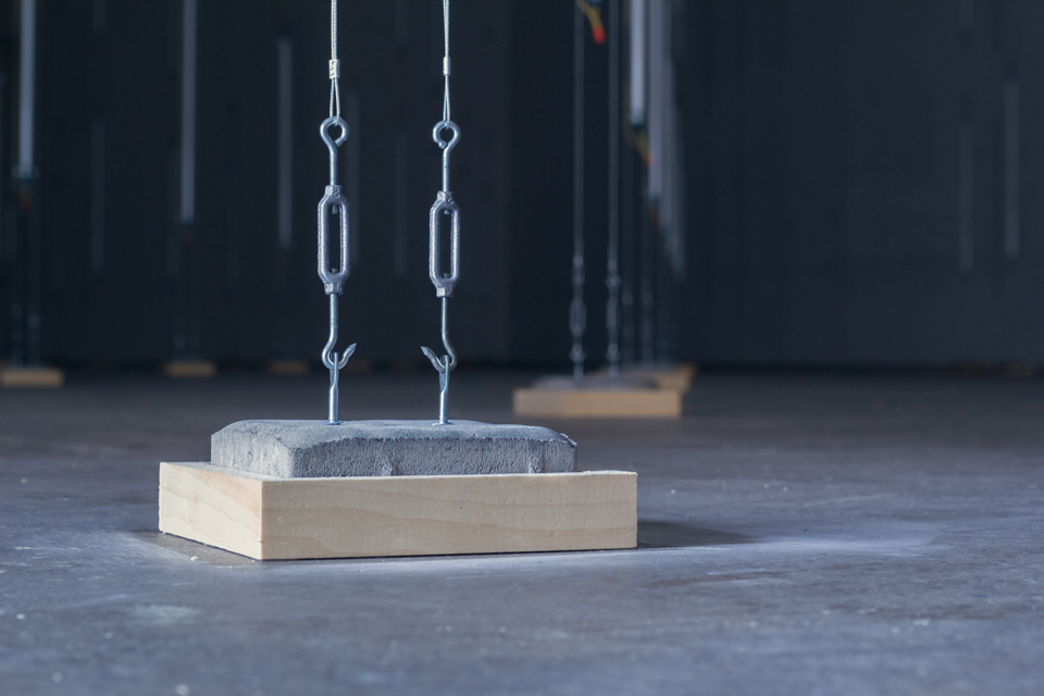
The columns of lights were not touching the floor. Two steel cables were tied to the ceiling and ran vertically down to attach to a concrete paving stone. Each of the 61 columns was essentially a plumb bob. A block of wood glued to the floor prevented them from swinging around, but the plumb-bob feature meant that each one was perfectly vertical. The light tubes were secured to the steel cables using brackets that Ezra and the volunteers hammered out from flat brackets. The wires that ran power to the lights dropped down parallel to the steel cables. At the top of each column was a wooden plate with terminal blocks to attach the wires. This made installation a lot easier because some of the work could be done on the ground.
The Performance
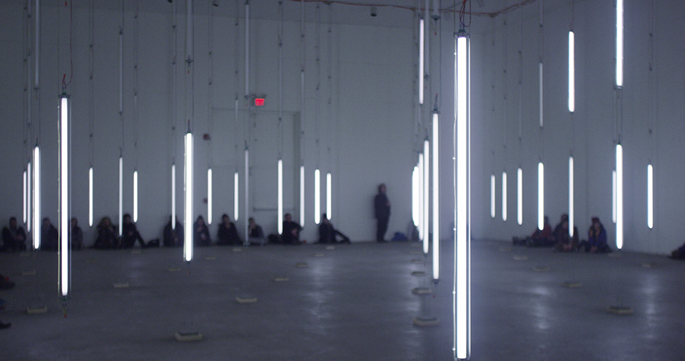
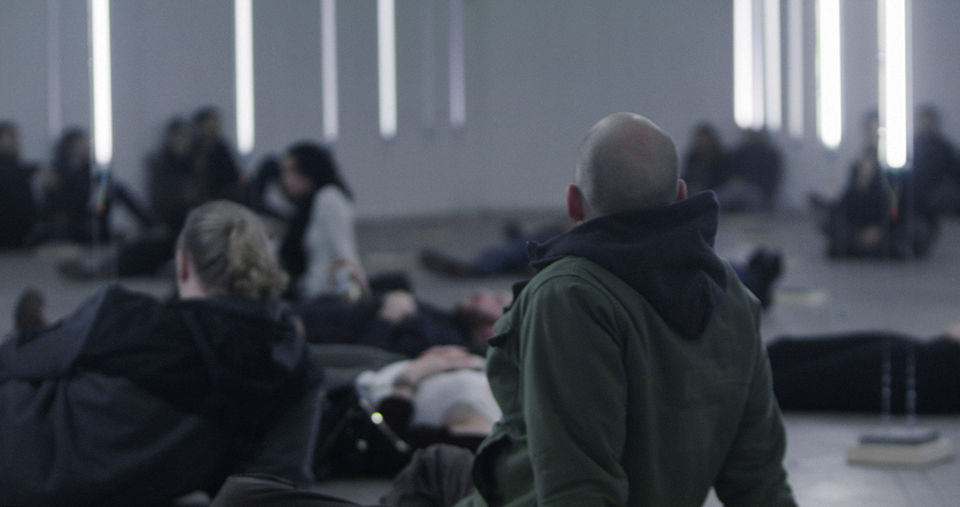
We had a preview performance for the volunteers and kickstarter funders, and then we had two performances that were free and open to the public. We also ran the show a few times for the professional videographers (and I’ll post their footage when I get it!)
The shows went great, they were well-attended and there were very few technical issues. The audience seemed transfixed by the flashing lights and reverberating rhythms. Some people layed on the floor and stared up, and others sat against the wall in order to see as much as possible.
What we learned
- The wiring between instant-start fluorescent ballasts and the bulbs is subject to capacitive loading and should be as short as possible (<16′) or else the bulbs might be erratically dim and/or flickering. Luckily this added some “texture” to the otherwise all-white room and all-white lights, but it was an annoying technical detail that we weren’t prepared to overcome because we only realized it after all the wiring had been done.
- LEDs might be worth trying out next time, since fluorescents can only be flicked on/off so many times before they fail.
- It’s very hard for a drummer to play six distinct dynamics on each drum (pp, p, mp, mf, f, ff). It’s even harder to jumper between arbitrary dynamic levels on multiple drums at the same time while keeping a rhythm going. More than 2 days of practice would be necessary for even a very advanced drummer.
- It’s very hard electronically to separate an analog mic signal into six different bands of peak amplitude. Using a low-pass filter on the hi-hat helped a lot (as well as peaking it out before the filter, which made it sound like a tom-tom drum after the LPF). Setting the knobs to pick out six distinct bands was very touchy. Next time we might try a true envelope follower, or perhaps a DSP engine. We might also need to use something else besides a contact mic (perhaps a force-sensing resistor on the drum head?)
- A bunch of people can come together and make something amazing happen!
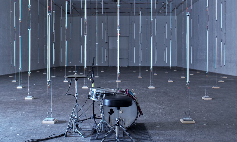

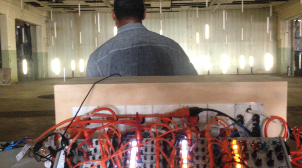
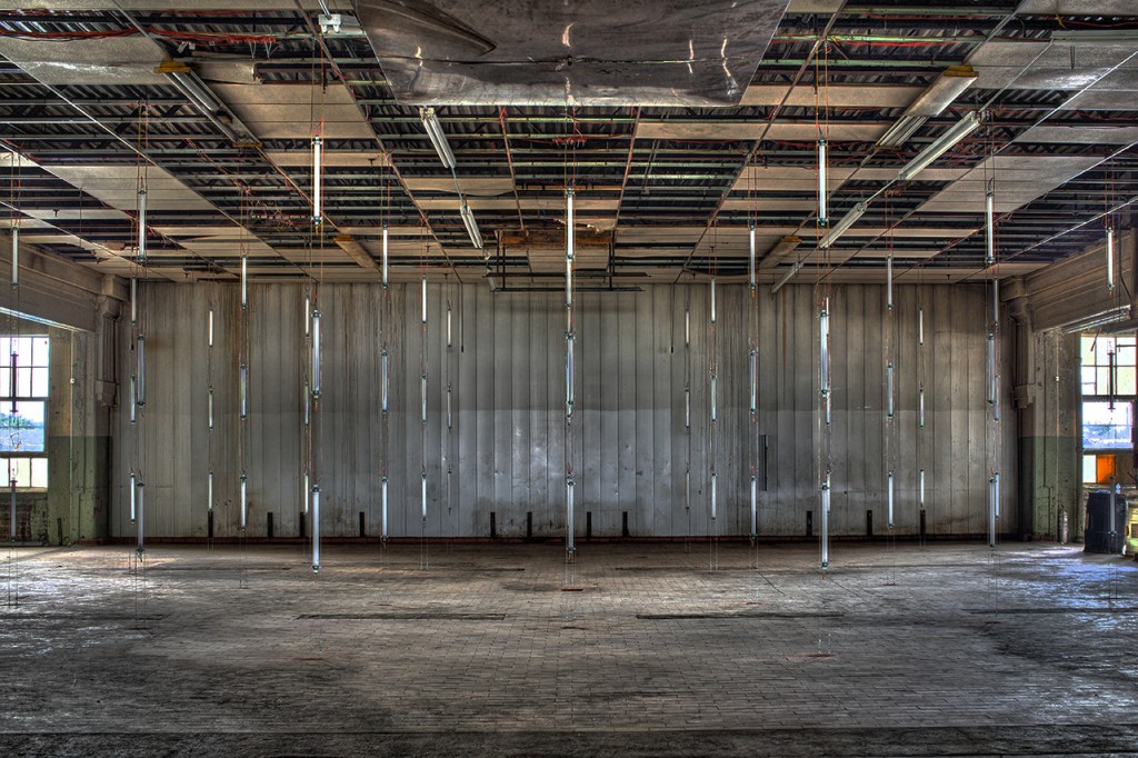
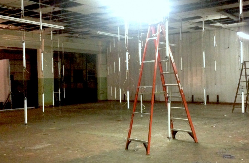



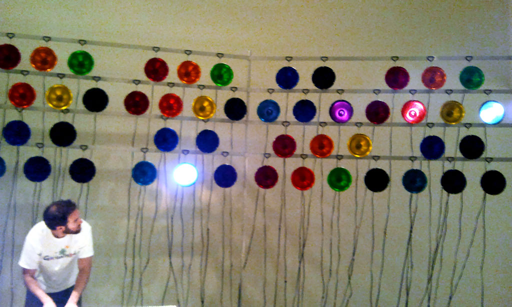

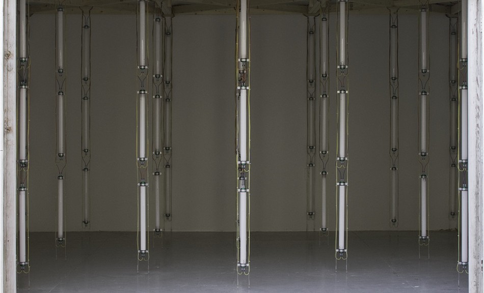
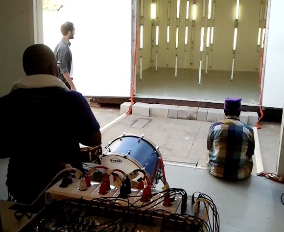
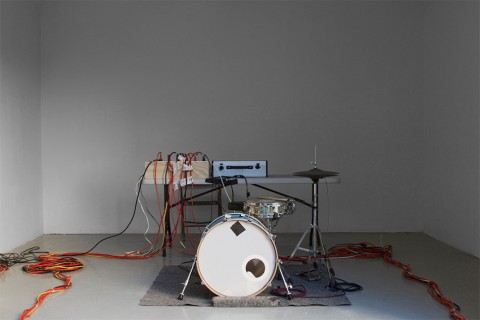
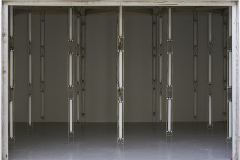 The lights were fluorescent tubes standing vertically in columns in an empty room, 69 lights total. Each column was made of 3 tubes (bottom, middle, top), giving us three layers of lights. The bottom layer was controlled by the kick drum, the middle layer by the snare, the top layer by the hi-hat. Also, the columns were arranged in 4 concentric rings that corresponded to the 4 amplitude bands (loudness response). So there was a center column, then a ring of 6 lights around that, then another ring, and a final perimeter along the edge of the room. A soft tap on the drum would just trigger the inner lights. A medium hit would trigger the center light and one or two rings around that, and a hard hit would turn all the lights on (for that layer only).