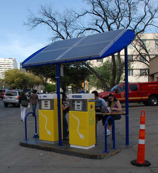

Sol Design Lab’s Solar Pump, a solar-powered charging station for mobile electronics, was an official part of South-by-Southwest this year. The stations have standard outlets, so anyone can walk up and charge a cell phone, laptop, or even an electric bike or scooter. The power comes from solar panels on the roof of the stations, so there’s no charge for charging (sorry… couldn’t resist). Refurbished 1950’s gas pumps provide a retro-future look that catch the public’s eye and twists the concept of “fill-up station”.
We set up three stations throughout Austin, including a large station downtown by the convention center, a smaller “pump” outside the South Lamar Alamo theater, and a mobile “pump” at Auditorium Shores. The Solar Pump grew out of Beth Ferguson’s MFA project, and these represent the third generation of prototypes.

My main role was the design and construction of the digital display, which used LEDs to indicate solar panel voltage, power output (to the inverter) and battery bank voltage. More technical details below….
Each station is a little bit different, with either 2 or 4 deep cycle 100AH 12V batteries creating a 24V system. A 1100W inverter supplies standard 110VAC power to the user through a GFCI outlet (including a big red Emergency-Stop button!). Between 2 and 4 bi-facial Sanyo solar panels charge the batteries through a Morningstar charge controller. We used the Pentametrix system to read the shunts and voltages, and then send that data digitally over RS-232 to the custom digital display module.

Tech details
Here’s the schematic:

Here’s the code (avr-gcc, using AVR Studio 4): solarpumppanel.c
Software
An Atmel AVR ATmega32A chip is at the core, communicating with the Pentametrix meter over a serial cable. The AVR makes a “request” to the Pentametrix every 500mS or so, and the Pentametrix responds with the latest readings: voltage on the solar panels, voltage on the battery bank, and current flowing out of the batteries to the inverter. The AVR then scales and converts these numbers and outputs them to the LED displays. The UART runs at 2400 baud, and the final byte is a checksum. If the checksum is off, or if the AVR doens’t hear a response from the Pentametrix, an error light goes on inside the box. Not terribly useful for debugging on the field, but on the bench this was handy.
Hardware
A Max232 chip handles the RS232 voltages, converting RS232 levels (-7V/+7V) to/from TTL levels (0V/5V). This directly connects to the AVR’s UART pins (RX/TX). These chips rule, they are totally worth the cost and board space.
Driving the LED displays turned out to be a little harder than I originally thought because the super-bright displays we found drop 7.4V, which is obviously higher than the 5V the AVR chip runs on. So I had to use an NPN/PNP transistor pair for each blue LED digit to switch +9V. (Q4/Q4B, Q5/Q5B, Q6/Q6B). This turned out to work well once I became OK with modifying the PCB and changing the code invert the “on” and “off” signals on the AVR pins for the blue digits only.
The yellow digits drop much less voltage, so I ran them on +5V and only needed on PNP transistor per digit (Q1, Q2, Q3). I’ve used the 2N5401 PNP transistor with good results for switching LED segments in other projects, and also have seen it around in the Peggy project… it’s fast and can drop a good amount of power… a keeper.
Finally, there’s a “bar graph” LED display which is 5 sets of LEDs, with 4 LEDs in parallel in each set. Each LED set is a different type of LED so they have a trimpot to set their brightness. I used the same 2N5401 PNP transistor on a 5V rail for these.
I went super-conservative on the powersupply, dropping the original 24V down to 18V, then to 9V, then to 5V.
Oh did I mention I found Pink LEDs! Yeah!!
Enclosure
Beth and drew up the front panel graphics in Illustrator, and I sheared some panels from 2mm aluminum. I then took that to a friend with a mill, who cut the rectangular holes for the numerical displays. I drilled out the round holes figured out a (perhaps excessively elaborate) way to mount the PCB to the front panel, and bend a flanged box to shield the circuit from the rear. The front panel is the main structural element and is mounted to braces which mounted to the frame of the pump.
I powdercoated the front panels white, and then applied the graphics with a decal, and baked that on. It came out pretty nice!
i just wish that they could soon reduce the cost of solar panels coz it is still expensive,:.
This is such a cool idea. They look great and very functional. Hope the idea catches on. Could use more of this ingenuity around the globe.
Thanks so much for sharing this it’s very inspirational and has made my day.