How to make an RCD Breakout
Intro
The Rotating Clock Divider is a Euro-rack format module from 4ms that takes an incoming clock signal and outputs 8 simultaneous divided clocks, each in the range of /1 to /64. It also has a Rotate CV input that re-assigns the divide-amount on the jacks. More information is at 4mspedals.
The RCD features 6 jumpers that can control various features. The User Manual goes into depth about what these do. The breakout panel is a way to bring those jumpers to the front, so you can use flip switches to change the jumper settings on the fly.
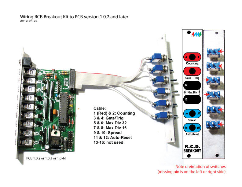
For PCB version 1.0.2 and later….
You will need:
- RCD with PCB 1.0.2 or later (see the bottom for instructions on pcb version 1.0.1 and 1.0)
- 4HP panel
- 6 SPST switches
- 16-conductor cable with a 2×8 connector on one end (standard Doepfer power cable, cut in half).
Here’s how it goes together in a nutshell:
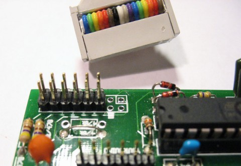
Let’s start by looking at the connection to the board. There’s only 12 pins on the board, but the connector has 16 holes. That’s OK! Just let the bottom four holes hang off (those four wires don’t go to anything anyways, as you can see in the first diagram). To be clear, by the “bottom four holes” I mean the four holes on the right hand side in the photo below (they are on the bottom in the photo above). The edge of the connector should not stick over the edge of the board.

OK, now let’s look at the wiring of the panel. There are six switches, each has two connections.
Notice the Max Divide 1 and 2 switches are flipped from the other 4 switches: the lugs are on the right side. That’s just because of the way I labeled the panel (which is the same one included in the 4ms kit, so do it exactly like this if you got the panel in the kit). For the top two switches, flipping the switch lever to the left will open the connection (same as removing the jumper) and flipping it to the right will close the connection (same as putting on the jumper). For the bottom 4 switches, flipping the switch to the right is like removing the jumper, flipping to the left is like installing the jumper. See the User Manualfor a description of what the jumpers do!
PCB version 1.0.1 (and 1.0)
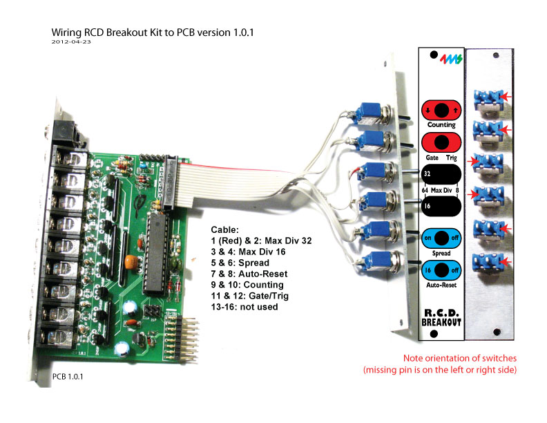
For PCB version 1.0.1, it’s the same process, but the switches are in a different order. Using the same cable above, it goes:
1 (Red) & 2: Max Div 32
3 & 4: Max Div 16
5 & 6: Spread
7 & 8: Auto-Reset
9 & 10: Counting
11 & 12: Gate/Trig
13-16: not used
Obviously you will have to upgrade your chip firmware to v1.1 if you want to use Gate/Trig or Up/Down counting or Spread. You can read about upgrading on the RCD page on 4mspedals.com
PCB version 1.0
For PCB 1.0, there’s only 4 switches hard-wired to the breakout connector pins, so you have to solder wires from the back of the PCB to some jumper pins which you insert into the breakout’s connector. Look at the photo:

You will be soldering the red, yellow, and black wires from the PCB to the back of a 4-pin (2×2) connector. Note that the black wire connects to BOTH pins in a row, but the red and yellow wires connect to one pin each. The inset photo shows the back of the 4-pin connector.
To use your new 4-pin, just push it into the breakout’s 16-pin connector where the Up/Down and Gate/Trig jumpers are supposed to go. Follow the pin numbering from the PCB 1.0.1 section (above). The red wire is Up/Down and that should be closest to the existing breakout pins. The yellow wire is next to the red, farthest from the existing pins. The black wires should be on the top.

